Basic Blink example for dsPIC30F4013
20 November 2016 at 7:25 pm
With an Arduino, I can teach someone to blink a LED in 15 minutes. It will always work. In the world of PIC microcontrollers, there’s nothing “that just works”. To help others trying to make a dsPIC30 family microcontroller do just the simplest thing, I’m posting this mini tutorial including what they expect you to know and what you actually need to know.
The Arduino community has always been a place where newcomers could feel welcome. Even the simplest questions are answered politely and nobody looks down on someone just learning the ropes. In general, it’s a very welcoming platform. You just download the IDE, plug the Arduino in via USB and you’re already moving. I’ve now tought microcontrollers to students for 4 years and they really love using Arduino as their first hardware tool. So what’s different with the microcontrollers from Microchip you may ask? The answer is simple - everything!
What they expect you to know
For a freelance project I’m working on, I have a piece of hardware designed in the US. It’s using a dsPIC30f4013 and it has been doing it’s job for many years without major problems. Now I’ve been tasked with adding new features into it and it’s been very interesting to see how the culture around the product is extremely different.
In the Arduino world you are expected to be a beginner, but in the PIC-world you are expected to be an expert - even if you’re just starting. Let me illustrate this with an example from this thread where a guy starts off by saying he is an absolute beginner and that he just wants to blink a LED.
Here are some of the comments he receives:
Refer to your micro datasheet. bye!
Do you have access to a logic probe or an oscilloscope to check if your crystal is oscillating?
And anyway I cannot see your CONFIG settings…
you need a pullup on MCLR, and a small bypass capacitor (say 100nF) mounted as close as possible to each pair of power pins
The first of these comments is just terrible? The datasheet for a MCU (like the dsPIC30F4013 that I am using) is no less than 221 pages. The worst is - that is just the parts that are specific for that single MCU. To get the full picture, you also need the datashee for the family of CPUs. For the dsPIC30F family that is no less then 772 pages! To top this off - to use anything remotely advanced, you’ll also need to study the dsPIC Language Tools Library. These 400+ pages detail how to use core features like UART, SPI and I2C - all features that an Arduino user will explore within the first few days of use. With a PIC, you should read almost 1400 pages of dense and highly technical documentation BEFORE even blinking a LED?
I can’t even imagine how long it would take to read close to 1400 pages? These manuals are not written for a beginner. I would say that datasheets in general are written by engineers that want to impress other engineers. Its not light reading, but requires focus so it’s quite tiresome for most to read.
Regarding comment #2 - how on earth can you expect someone that says he is a beginner and cannot blink a LED to have a logic probe or an oscilloscope? Regarding #3 - what CONFIG? Now - I know that config is important when it comes to PIC, but I have yet to find a good tutorial that explains how that is done correctly. I know it’s in the datasheet, but the text here really isn’t meant for beginners.
Comment #4 is actually quite good, but I’d guess it’s somewhat confusing to a beginner? The pullup is essential, but the capacitors are not required to get this working. You would be wise to have them in a PCB design, but they are really just complicating things for beginners trying to blink a LED.
What you REALLY need to know
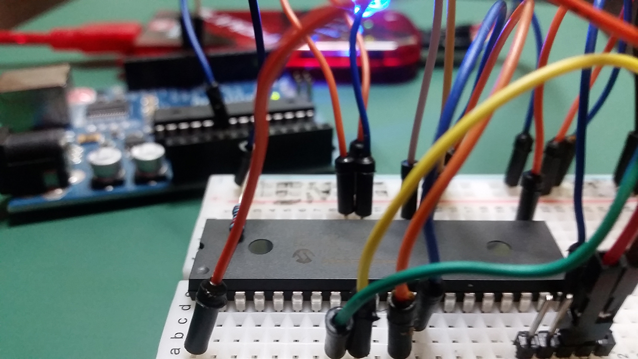
To get a bare bones dsPIC30F4013 up and running blinking a breadboard, you will need the following:
- DIP version of the dsPIC30F4013
- 10K ohm resistor
- LED
- 220-510 ohm resistor (for the LED)
- PICKIT 3 programmer (or similar)
- breadboard
- Jumper cables
Locate the datasheet for the dsPIC30F4013 and find the page that explains the PINOUT.
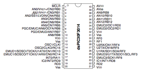
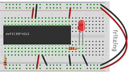
Pin number 1 is marked with a dot on the chip. The text next to the pin shows that this is the pin with the MCLR function. We’ll need that later. Place the chip so that pins 1-20 align with the numbering on the breadboard. Connect the 10k resistor from pin 1 (MCLR on the datasheet) to the 5V rail that runs along your breadboard. Connect all the pins marked as Vdd to the 5V rail and all the pins marked as Vss to the minus/ground rail. If you use the power rails on both sides of the breadboard, make sure you connect the minus on one side side with the other and the same for the 5V rail.
Next, connect the shorter PIN on the LED to Vss (minus/ground) and the longer to one end of the 220 ohm resistor. The other end of the resistor should go into the hole connected to Pin 19 (marked as OC4/RD3).
That’s all that is needed for the Microcontroller itself. Now we need to connect it to the programmer.
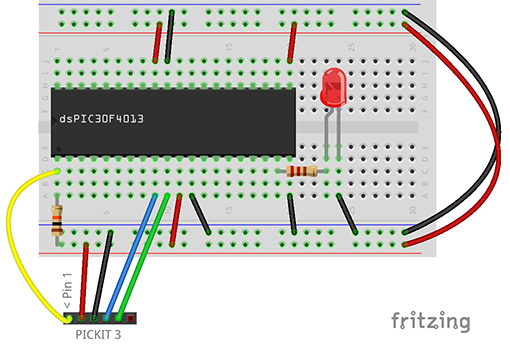
On the PICKIT 3 programmer, there’s 6 pins and one is marked with a small arrow. This is Pin 1. Here’s how you connect the various pins:
| PICKIT 3 | dsPIC30F4013 |
| Pin 1 (MCLR) | Pin 1 (MCLR) |
| Pin 2 (Vdd) | Vdd (5V power rail) |
| Pin 3 (Vss) | Vss (Ground rail) |
| Pin 4 (PGD) | Pin 9 (PGD) |
| Pin 5 (PGC) | Pin 8 (PGC) |
Note that these pin numbers will only be correct for the dsPIC30F4013. Other variants will need to use different pins, but you can locate these by looking at the correct datasheet.
With that connected, it’s on to the code.
The code and the config
There are several things that are difficult to know that is required. The main reason for this is the absolute lack of good resources when it comes to tutorials and examples. MicroChip has examples in both the docs and online, but few of these are suited for beginners. The online examples are not publicly available in search engines. They are listed in a cumbersome tool that tries to be smarter than Google that allows you to filter. It’s not smarter than Google and Google will never find and index these example files since they are ZIP archived.
Anyway - there’s a few things you need to know before starting:
- What to download
- How to setup
- How to set the frequency
- How to configure
- What to include
Start by downloading the MPLAB X IDE. This is modern IDE that has the features you’ll need, but it’s impossible to make it work on anything other than Windows. It comes with most, but not all the features you’ll need. If you need to use Legacy libraries, you’ll need to do some digging to find these. The normal download is sufficient for the LED example, but there’s one confusing thing you must resolve - what compiler should you download? You’ve got to hand it to the people that named the microcontrollers from Microchip - they really did their best to confuse people! In my case I have a dsPIC30. Should I use XC8, XC16 or XC32?
For obvious reasons you would think that what compiler to use is mentioned in those almost 1000 pages of datasheets, right? Well, it isn’t. You need to KNOW that the dsPIC30 is a 16 bit Microcontroller and that for any 16 bit microcontroller from Microchip you should use XC16. It amazes me that nobody thought of distributing all 3 compilers with the IDE and then just automatically select the correct compiler. The IDE will know what compiler to use when it’s time to compile the projects since you have to tell what microcontroller it’s working with. That brings us to the next part - setting up a new project.
Setting up a new project is fairly simple using the MPLAB X IDE. Select File -> New Project -> Microchip Embedded -> Standalone Project. Select your chip family and device and click through the dialogues. This only does the project setup. It doesn’t even set up a single source file, so you’ll need to right click the Source Files folder in the Projects window and then choose New -> mainXC16.c. You can rename this to anything you want (like main.c). This newly created file is more or less empty, but it does include the xc.h file that in turn includes the basic files for your microcontroller.
Next you need to know what frequency that your dsPIC30F will be running at. In most examples, this is referred to as FCY and the value of this is confusing. It varies across different microcontrollers, so you can’t just use one you found in an example somewhere online. You’ll need to search the datasheet for the “Oscillator Operating Modes”. This is a long and confusing list of basic clock speeds that your microcontroller can run at. It is however easy to find the one needed for this example. Since we have no external clock signal attached, we need to use the internal oscillator built into the microcontroller. According to the datasheet, this is 7.37Mhz and you can find this set in the example below as SYS_FREQ.
Another important thing is to set the FCY variable. On this specific microcontroller this should be SYS_FREQ/4, but figuring this out is difficult. Reading the datasheet you can see that FCY =1/TCY. So what is TCY then? It’s the “Instruction Cycle Time” dummy, don’t you know? Well how on earth could I? Digging further I find that TCY = 1/MIPS and that MIPS = (FOSC*PLL)/4. So now you need to know what FOSC and PLL is then? Figuring that part out is difficult if you’re not using either an external clock or crystal (if you’re experienced enough to know what that is), but lets just leave it at that?
Next up is the CONFIG mentioned in one of the comments. Few beginners include this since ... it just looks insanely complicated I guess? It isn’t all that hard, but it does require some former experience to get this right. What looks scary is all those FWPSB and WDT’s. Luckily there’s a tool built into the MPLAB X IDE that can set this up for you Window > PIC Memory Views > Configuration bits. In this dialogue, you tell the tool what oscillator you are using (hey, didn’t you already do that?), prescaling, watchdog and lots of other things that beginners really should not have to know… I understand that it’s there for the advanced users, but to become an advanced user you just need to get a stupid LED blinking first, right?
Behold - now you’re ALMOST there! The last thing you need to know (without anyone telling you) is that to just wait a little on a PIC you can’t just use the builtin “delay” function. Why? It’s not builtin… Include the libpic30.h file that includes the second most required utilities for the dsPIC30F family and your projects should compile. Phew!
// Useful advice! http://www.microchip.com/forums/m790211.aspx
// FCY must be defined before the includes or things go wrong.
// For some odd reason, the config tool does not set this based
// on the MCU + Oscillator selected
#define SYS_FREQ        7370000L
#define FCY             SYS_FREQ/4

//*****************************************************************************
// Device Config; generate using Window > PIC Memory Views > Configuration bits
//*****************************************************************************

// FOSC
#pragma config FOSFPR = FRC             // Oscillator (Internal Fast RC (No change to Primary Osc Mode bits))
#pragma config FCKSMEN = CSW_FSCM_OFF   // Clock Switching and Monitor (Sw Disabled, Mon Disabled)

// FWDT
#pragma config FWPSB = WDTPSB_16        // WDT Prescaler B (1:16)
#pragma config FWPSA = WDTPSA_512       // WDT Prescaler A (1:512)
#pragma config WDT = WDT_ON             // Watchdog Timer (Enabled)

// FBORPOR
#pragma config FPWRT = PWRT_64          // POR Timer Value (64ms)
#pragma config BODENV = BORV20          // Brown Out Voltage (Reserved)
#pragma config BOREN = PBOR_ON          // PBOR Enable (Enabled)
#pragma config MCLRE = MCLR_EN          // Master Clear Enable (Enabled)

// FGS
#pragma config GWRP = GWRP_OFF          // General Code Segment Write Protect (Disabled)
#pragma config GCP = CODE_PROT_OFF      // General Segment Code Protection (Disabled)

// FICD
#pragma config ICS = ICS_PGD            // Comm Channel Select (Use PGC/EMUC and PGD/EMUD)

//*****************************************************************************
// Device Config /end (paste config between these two)
//*****************************************************************************

#include <xc.h>
#include <libpic30.h>

int main(void) {
    _TRISD3 = 0; // set D3 to output
    _LATD3 = 1;
    while(1)
    {
        _LATD3 = 0;
        __delay_ms(1000);
        _LATD3 = 1;
        __delay_ms(1000);
    }
    return 0;
}
Oh? you don’t know what those TRISD and LATD’s are? Well _TRISD is what Arduino calls pinMode, you know the method you use to set the mode of a pin? And yes - setting _LATD3 to 1 is similar (but not too similar or explanatory) as the Arduino digitalWrite method. Obvious once you know it, right?
You must be kidding, right?
No I’m not. It does sound like a joke, but it really is this convoluted to get a simple LED blinking. This is the exact reason that Arduino was founded - to be a counterweight to this elitist, top down world. I should note that I have seen similar things on the AVR Freaks forum also, but not this bad. I should also point out that the hardware itself works great, it’s just incredibly hard for beginners to learn how to use it. One might argue that you can’t compare a chip manufacturer to a platform like Arduino that use many different chip’s in their designs. I’m not really comparing hardware here - I’m comparing the developer experience for beginners. As a teacher, that is a concern for me. If you start with an Arduino (like most do these days) you expect solutions to be that easy to work with in the future. If you come from Arduino, then you’ll instantly dismiss PIC as being unnecessary difficult. This is hardware, so you’ll loose slowly but you will eventually loose completely.
The forum thread mentioned above is not unique. After working with PIC the last months, I can tell that this top down view persists across the entire forum and unless you prove worthy you won’t get an answer. Developers from across the world are fleeing solutions based on PIC controllers. There is no reason you should have to pay the massive extra cost of poor documentation and a lack of examples. Even Chinese chip manufacturers such as Espressif (the makers of the popular ESP8266) managed to make better tooling and API within a year. Microchip should really look to companies like Particle and Electric Imp that sell advanced microcontrollers with builtin wifi and hardware encryption/decryption. Their APIs are super solid across multiple devices and they just work. If they want to be really impressed, they should study Paul Stoffregen’s work on the Teensy. It’s so much cool stuff happening in the microcontroller world, but Microchip isn’t part of it.
PS: I know that Microchip makes lots of other things apart from Microcontrollers. It’s just that this blog post is about just that and not the other things they do like sensors.
PPS: If you go to the Microchip website after reading this - they have an error in the website JS so no links will open normally in Chrome. Just right click and select “Open in new window” to view the pages. If you open the console, you can see that the error thrown is “Uncaught ReferenceError: ga is not defined” referring to the Google Analytics implementation that is broken.