Tiny Microchip MCU’s reference boards
23 May 2026 at 1:13 pm
Some months ago I started a project where I needed a microcontroller with just a few pins and a DAC. After some digging, I came across the ATTiny1-series from Microchip. Worked great for the task and after finishing that project I found it's "cousin MCU" series - the AVR64DD14. Both are very good on price/performance and they exist in 14-pin SOIC packages, making them DIY friendly.
It's not that they don't come in other packages though. If you need more pins, there's compact VQFN variants with lots more pins and peripherals:
So while the RP2350 series are nice, these are smaller, lower priced, requires no extra parts and have several unique features such as the DAC and ZeroCrossing detection. They're also very nice to work with in Arduino & PlatformIO thanks to Spence Konde's great projects megaTinyCore and DxCore. I also recommend checking out the blog Technoblogy.com that has lots of great projects & howto's for these MCU's.
What makes them so easy to work with is the fact that you don't need any external components. The Reset pin has the sensible builtin pullup, the internal oscillator is good enough for SPI and other things, there's a full set of good peripherals: SPI, I2C, ADC, DAC, PWM, UART, RTC, Timers and AC pins. All pins support interrupts and for the AVRDD series there's a good mux of pins as well. There's a good variety of Flash/SRAM/Eeprom sizes as well and they're both programmable via the UPDI protocol. The main drawback is of course that they're 8-bit, but for many tasks that isn't relevant. The main attraction here isn't the FPU, but rather the small size/low price vs features. Overall, great parts that I enjoy using, so I thought I'd share my experience. By now I've used both 8, 14 and 32 pin variants of both families.
The reference boards
Whenever I start working with a new microcontroller, I want to create a minimum setup of the MCU. In this case, it's literally just the chip. Since you also need an UPDI programmer, I figured it made sense to add one of these to the boards as well. I designed it so that the programmer can be cut off from the main board in case you just need one of the two.
The overall shape is the most compact of these starter PCB's I've made, leaving space for plugging in 3 wires for each pin on both sides of the breadboard. It's very minimal, with just a user controllable LED and button. To just test a chip, this is all you need if you have all other pins & peripherals easily available via pins? Strictly speaking, the reset button on this board isn't needed since the SerialUPDI programmer takes care of that part.
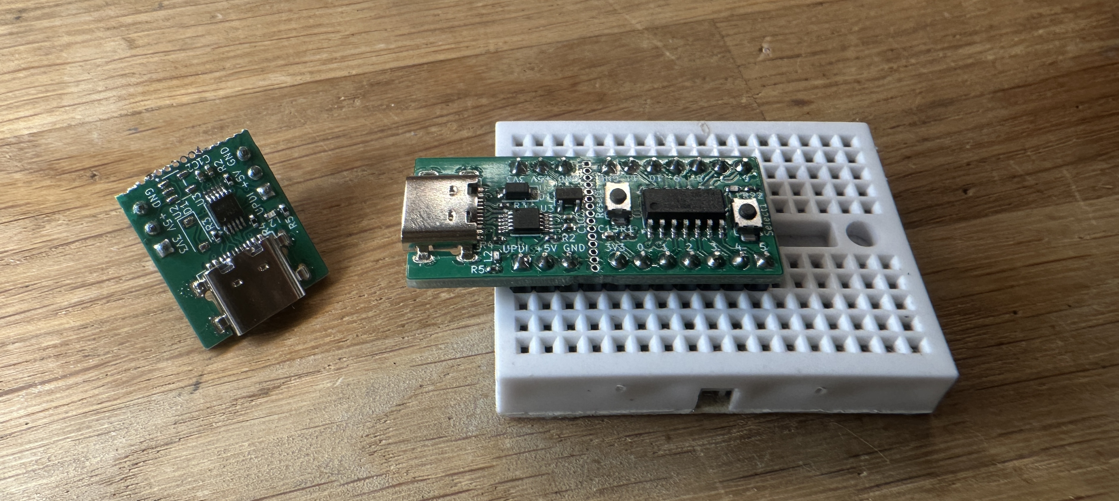
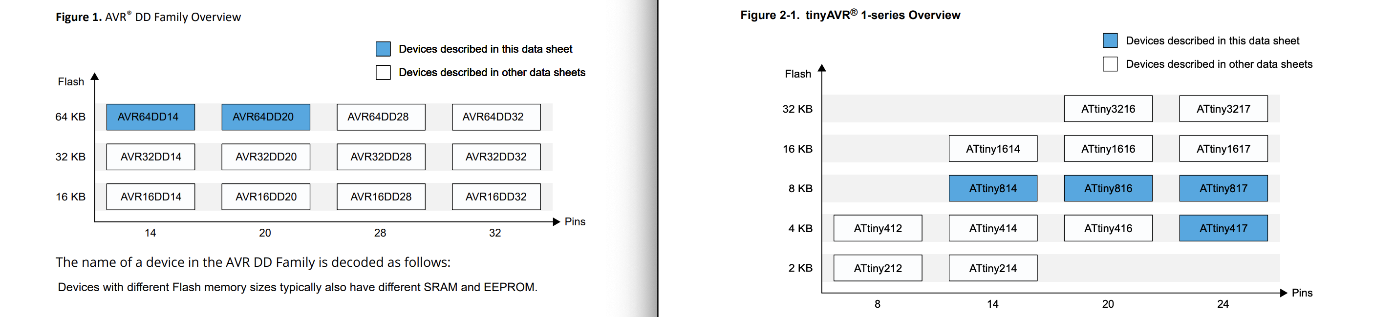
Unfortunately, the first iteration wasn't exactly breakable by hand, but with a pair of plies, you can easily separate them. My 4 test boards all worked smoothly, so the files for the ATTinyX14 series (ATTiny214, ATTiny414, ATTiny814, ATTiny1614) are well tested in multiple projects by now. The board can be used with any of the aforementioned 14-pin variants, depending on your need. The first part of the name is the amount of Flash and the second is the number of pins, so the ATTiny1614 has 16Kb flash. The ATTiny814 has 8Kb flash and is a 14-pin SOIC.
As mentioned, I later came across the AVRxxDD14 series and made a reference board for these also (AVR16DD14, AVR32DD14, AVR64DD14). Just as for the other series, the first number indicates the amount of flash memory available and the second is the pin count. The DD indicates which of the MCU series this is from. There is DA, DB, DD, EA, EB and the DU-series, but only the DD series has low pincounts.
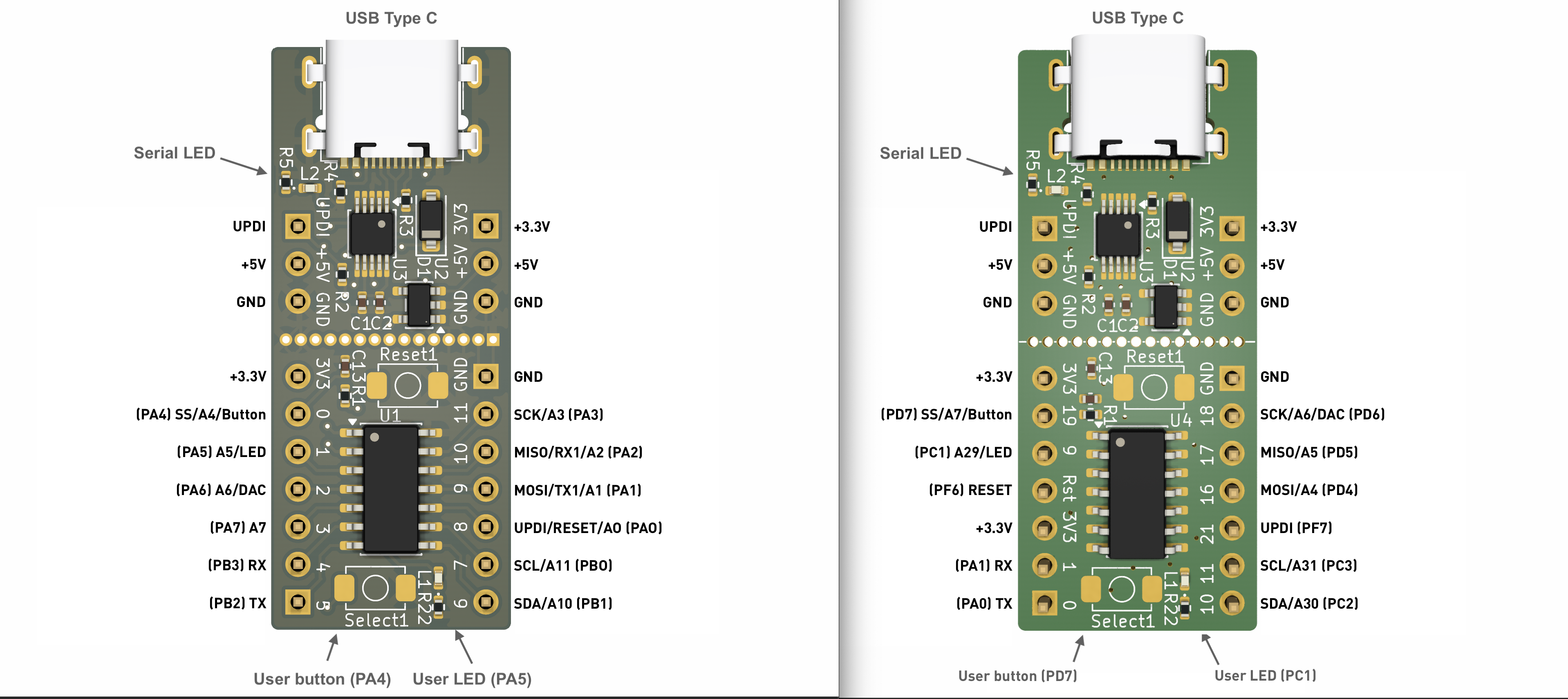
Given that these are both an 8-bit MCU in 14-pin SOIC, it would be brilliant if they were pin compatible, but for some reason Microchip failed to do that. Just to make this the worst possible case, they even swapped the VCC & GND pins. If you use an AVRxxDD14 chip on the above test board for ATTinyX14, you would be reversing the voltage into the chip. In many cases, it's difficult for chip designers to make pinouts compatible, but power & ground is everywhere on a chip so swapping these is just … a poor choice? I've thus made a separate, but otherwise quite identical board for the AVRxxDD14, so at least these reference boards can be swapped when used in a breadboard. I'm still waiting to receive & test this design, but once it's verified, I'll update the github repo with the Kicad design files for this as well.
My reference design collection grows
These two boards go nicely into my collection of other reference/starter boards for microcontroller projects:
Here's the pinouts for both the new boards (as on top of this page):