Getting started with STM32F0
04 January 2019 at 8:35 pm
I use the Particle Platform a lot and these have been based on STM32F4 up until the new Mesh radios they just delivered. The STM32 series is massive. There’s microcontrollers for every need and budget, so I figured it would be a good learning experience to work with one of the cheapest ones available?
After some looking at datasheets, it looked like the STM32F070F6P6 was a good option for my POV-project. For just a few of these, you pay $1.5 per MCU. If you make something in volume (as in 2500), the price drops to $0.70 and below. If you only need a few pins, such an MCU can be a great budget alternative. It’s a full 32bit microcontroller with all peripherals you’ll typically need and it has the possibility of programming it via USB. It’s cheap but has somewhat limited options and not too many pins.
Getting it up and running
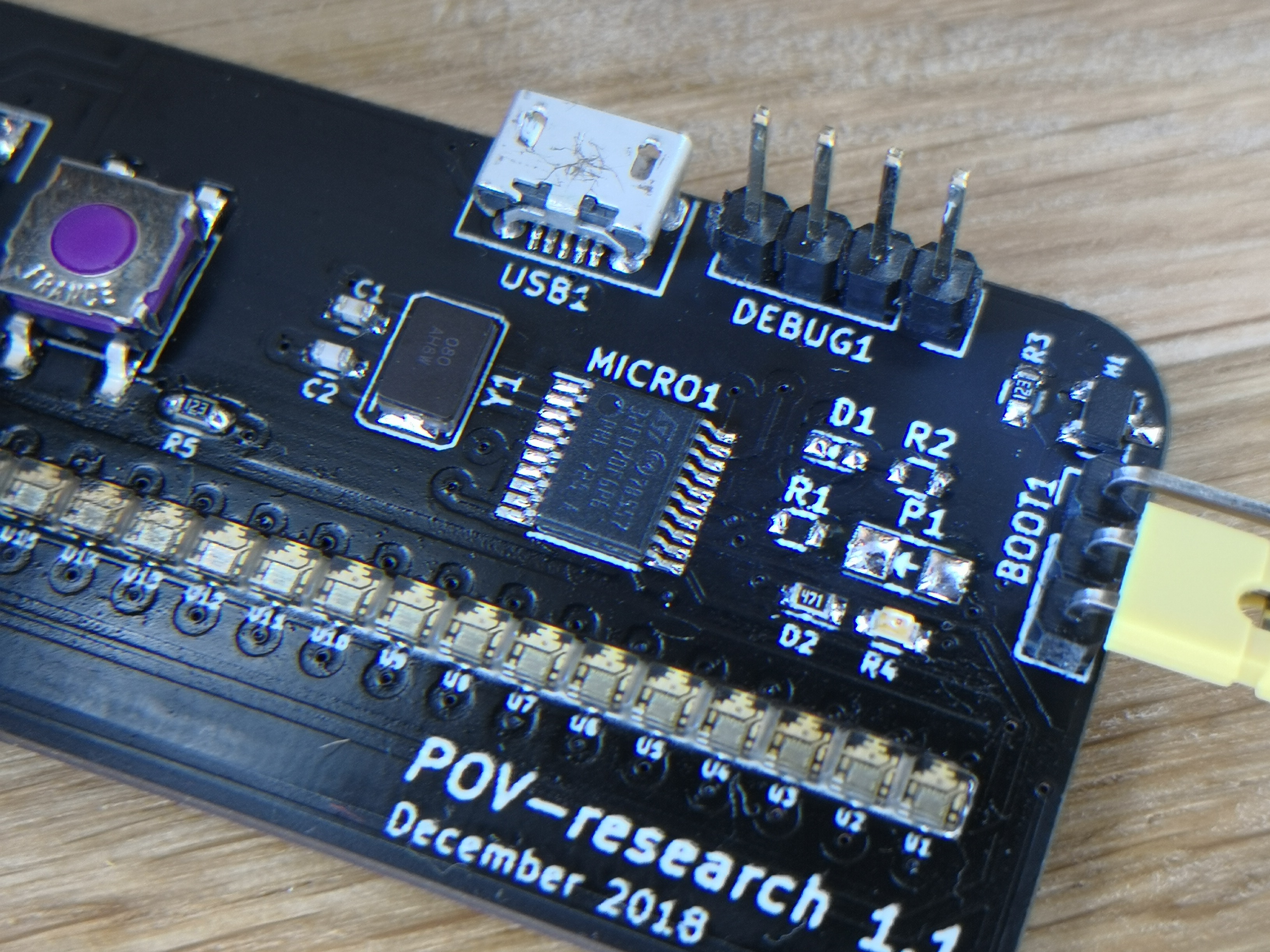
Getting it up was super easy. No external components are required to run at 8Mhz, so you just slap the chip on a board and add pins to program and debug it (SWDIO + SWCLK). You can find a STLink v2 programming adapter on Ebay for less than $2, so this really is an affordable development platform. The drawback of running the chip without a crystal is that the internal RC oscillator is not precise enough that you can use USB. On the second iteration of the board, I added the crystal, but then realised that you need to upload a custom USB bootloader as the chip’s don’t come with one as stadnard. I still have not figured out how to make this work with my IDE, but I’ll get there eventually. Speaking of IDE’s for STM32 - I’ve now tried a few and the development experience is far from the 1-click Arduino installer. They’re much more IDE’s than the Arduino glorified text editor, but the install process is not as smooth.
After testing some more it turned out that the STM32F070F6 line cannot use USB along with both I2C, Serial debug and Serial data. It simply does not have the required pins to do it? I can remap some pins to get USB working (PA9/PA10 -> PA11/PA12), but that prevents me from using an I2C based IMU. There is also the “minor issue” that the Virtual Com port driver takes up more than the available RAM in this rather constrained device… To work around this I’ll design the third version of the board based on the STM32F070CBT6. This is a 48 pin chip rather than just 20 pins. The price goes up to $2.26 per chip for 10+ and to $1.15 in volume. Its more expensive, but also offers 4 times the memory (128Kb) and that’ll come in handy to get USB working.
It also turns out that the MPU-6050 Accelerometer and Gyro I wanted to use is $8.31 from Digikey or Farnell? That’s for the IC alone. You can buy assembled MPU-6050 modules with all the required extra parts for $0.70 from Aliexpress. I already have 20 of them from another project, so I’ll just add holes to solder these modules in, rather than place them on the board. Reduces the price of each board and swift to solder in.
Setting up clock speeds and the rest of the hardware was really easy using the graphical tools provided in CubeMX. One of the very nice features of the STM32 family is that all pins can be setup as most anything. Want your analog pins on one side? Sure. Just set them up that way. Want two SPI controllers? Sure - just add them to the ports you want. The STM32F0 family is a little more limited than the STM32F4 that I’m used to, but they’re still quite flexible. You can also set this up “by hand”, but using CubeMX to generate a set of files to start from is quite smooth. Just select your IDE, and CubeMX will generate suitable project files and a setup for that IDE. The main file will be full of comments indicating where you should put your code. If you follow this, you can then re-run the CubeMX tool to change pin config at any time without it overwriting your code.
What IDE to use?
The first IDE that I tried out was Atollic TrueSTUDIO for STM32 9.1. For an integrated IDE on Windows, this was rather clumsy to set up. I got it working, but it was far from a one click installer? I had expected it to be more plug and play. For my Mac I setup System Workbench for STM32 from OpenSTM32. Having worked with several Eclipse based tools before, this was easy to setup but it’s kind of clumsy that the supplied downloads (both from OpenSTM32 and ST) have to be started from command line. ST supplies what looks like OSX installers, but these fail miserably and they’ve done so for many years. Given how popular Mac’s are with developers, it’s surprising that they don’t even document this but rather just pretend to have a working solution.
It’s also surprising that we still don’t have proper 1-click installers for stuff like this in 2019. It’s not super hard to install System Workbench with all required dependencies, but it’s far from simple for a novice. They do however provide great written documentation to follow.
Both TrueSTUDIO and Workbench works well. You get access to full debug capabilities via stlink + openocd and both IDE’s are completely free. Workbench is also Open Source. There’s also commercial IDE’s out there that support the STM32F0 family such as Keil’s MDK-ARM and IAR Systems Embedded Workbench. I don’t have $2-5k to drop on testing a platform on my spare time, but if you already have this software it’s probably a little smoother to get things up and compiling.
Working with it
STM32’s do not come with anything resembling an Arduino API, so it may take a little getting used to doing everything “manually” if you come from a more “managed platform”. To turn on an output pin, you do something like this:
HAL_GPIO_WritePin(GPIOA, GPIO_PIN_3, GPIO_PIN_SET);
To turn it off, it’s something like this:
HAL_GPIO_WritePin(GPIOA, GPIO_PIN_3, GPIO_PIN_RESET);
Lot’s of CAPS and everything is defined as constants, so having an IDE that has some intellisense to open and inspect is required. It’s nowhere near as “verbal” as Arduino’s digitalWrite, but its just another way to do things? If you play around with several platforms, you’ll soon realise that this is how it works in the MCU-business. Neither Microchip, Atmel, Parallax, STM or any other vendor offer APIs that resemble anything you know already. They all want you to go deep down and toggle registers on the chip rather than use convenient and familiar methods that can gloss over how the chip works.
They do however give you a hardware abstraction layer (HAL). It’s not anywhere near as complex as just working with registers, but it’s also not exactly smooth? To use GPIO you first have to enable the peripheral. Then you use the following commands to set a pin as ouput:
HAL_GPIO_WritePin(GPIOA, GPIO_PIN_3, GPIO_PIN_RESET);
GPIO_InitStruct.Pin = GPIO_PIN_3;
GPIO_InitStruct.Mode = GPIO_MODE_OUTPUT_PP;
GPIO_InitStruct.Pull = GPIO_NOPULL;
GPIO_InitStruct.Speed = GPIO_SPEED_FREQ_LOW;
HAL_GPIO_Init(GPIOA, &GPIO_InitStruct);
This is equivalent of Arduino’s single line pinMode command. No problem, it’s just more work. I’m sure this is MUCH faster, but in general I do not care if something is a little slower if it’s easier to remember. If all the code is Open Source so I can learn from it, that will save me in the very few and narrow cases where I need to save a nanosecond or ten? You could of course just write your own pinMode commands if you think this is how it should be.
I know some ppl that prefer to not use any tools and rather go for the 83 page manual for the specific chip, the 91 page programming manual, the 779 page reference for the family of chips or the many hundred of documents detailing how features such as DMA, RTC, PWM will work in detail. If you’re one of them - then good for you as you won’t need to worry about what to do with your spare time?
I on the other hand think good thing they made CubeMX to type all the config out for you and include HAL files 😊
It’s not what I’m used to, but it does the job well and I don’t mind learning multiple ways to skin a cow.