First proper speed bump
10 January 2012 at 1:37 pm
I love learning new stuff, but I hate to learn that something can’t be done. I spent most of this day trying to make things work, but in the end it proved impossible. I had gotten the RN-XV WiFly Module with a tiny Wire Antenna from Sparkfun, thinking that this would be perfect for remotely controlling my Arduino devices. On the product page there is a picture of the module on a XBee card and the text describes it as a drop-in replacement for Xbee hardware. I guess I need a Xbee shield then? and off I went to order the Sparkfun Xbee Shield from my local supplier Robonor, thinking this would ensure compatibility. Turns out that was wrong.
Spent first part of today visiting customers and friends as well as writing a tiny AIR app that’ll perform simple Telnet-communication. All the WiFly modules can be set up via Telnet and doing stuff like this is really easy in Flash / AIR.
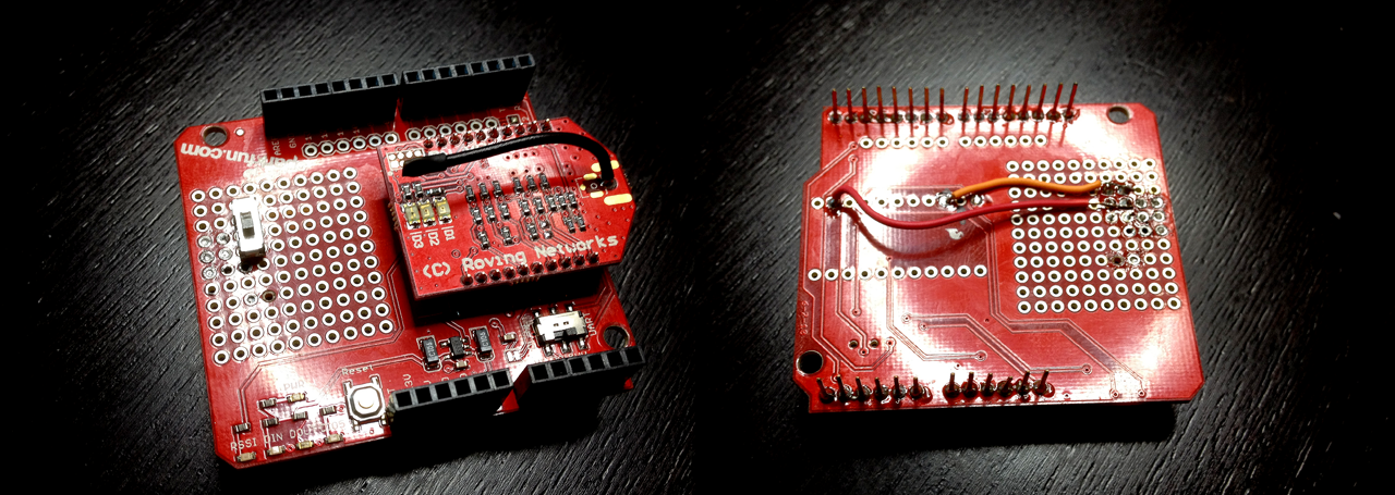
I spent most of the day getting the darn thing up and running. I first soldered the header pins and then made a small circuit on the proto area where I could toggle a switch to supply 3.3v to pin 8 of the WiFly to make it go into AdHoc mode. I prototyped the circuit on a breadboard first and the soldered a permanent version onto the Xbee shield prototype area. Then I realized that since I used the outermost holes in the prototyping area, the switch would touch the USB-in plug on the UNO beneath the shield…
I soon realized that desoldering isn’t very easy when all you have is solder wick, so now I’m getting a proper solder pump as well. I simplified the layout to not include a LED when AdHoc mode was on and moved the circuit a couple rows in. After measuring that the switch did what it should, I tested it and sure enough - the WiFly comes up as a AdHoc network that I can telnet into. That won’t let me control the Arduino though so it was time to code a bit.
Since the WiFly Shield is based on a quite similar chip, I figured that I could probably start by using those tutorials. It didn’t work right away, but there were some good comments on the WiFly SHield page. I got the shield to work in that I got a message from the WiFly chip saying:
WiFly Shield Terminal Routine<br />
	Could not initialize bridge, locking up.
This meant that I could not write to the device. Also - when the Xbee shield was on, it was impossible to program the Arduino. I kept getting the error message “avrdude: stk500_recv(): programmer is not responding”. I’ve read about this before and it’s usually a short circuit or something blocking the RX pin on the expansion board. I really got to use my magnifying lamp here… I traced all the circuits on the board, compared it to the datasheet for the RN-171 chip an the RN-VX. I couldn’t find a clue.
That’s when I realized that in the world of electronics - there actually is live human support! Coming from a software background I’ve gotten used to the fact that if something fails, you have to fix it yourself or pay extra money to get expert help. I called up Sparkfun and got to talk to their support ppl that told me to desolder a SMD diode and short it with a wire. That should prevent the programming problem. I did this, but had a hard time debugging if my soldering was working as when I measured - it didn’t show a connection. After another call to Sparkfun they told me where to measure and also said that when programming the Xbee shield, I had to toggle the tiny switch from UART to DLINE. After programming, it should be set back to UART. I had tried this before without success, but this time it worked! I could now program the Arduino without removing the shield. Apart from that - no dice. The support rep told me that he had not seen anything posted on using the RN-VX with the Xbee shield so it might not even be possible… Dead end in other words.
I’ve realized that I need to learn more about serial UART comms and how the I/O works. I’ll also skip the shield and use some test hooks directly on the RN-VX to see what I can get out of that. Fingers crossed that I won’t burn it up as it’s a bit sensitive to high voltage. Guess I’ll lower the current with a plain resistor? I’ll post my findings as I get to it but it could take a few days - I have to do some accounting or my wife will kill me 😊
(update Jan 16th: solved the voltage problem!)