ESP32 C3 gotchas
21 January 2024 at 3:14 pm

Lately I’ve been making a couple designs based on the ESP32 C3 chips from Espressif. These offer a nice tradeoff between performance and features and they’re ideal in small devices that only need a few pins. It does however act a bit differently than the other ESP32 chips such as the older ones and S2/S3, so here’s a couple things I’ve learned that may be of use to others.
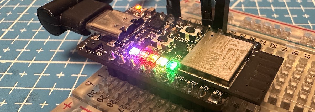
For this christmas, I made a small test board for the C3 that I gave as a gift to my son. He now studies electronics and he’s recently been working with RiscV chips, so I figured I’d give him his own DevBoard. I’ve published all the design files as Open Source hardware on my Github and I call it the ESP32 C3 Tiny - since it’s two breadboard rows narrower than the official C3 Devboard from Espressif.
The official board adds a USB to Serial chip, but since the C3 has a USB controller included, I wanted to test using this. It worked great and that means if you use the ESP32 C3 Mini 1 module, it’s possible to make really small things that should pass testing easily.
Making a board based on this module is just like any other modules from Espressif, but some core pins are different. It uses GPIO09 rather than GPIO00 for the BOOT button. This button allows you to put the device into DFU/Upload mode, so be sure to put a button on that specific pin.
I’ve read about others that have problems with Serial/UART output on this module. I’m not sure what the problem is, but note that you need to pass in the RX/TX pins to the Serial.begin method.
Strapping pins
On the C3 Tiny, I looked up the schematic from the Espressif DevBoard. As part of that, I put a 10k Resistor on GPIO08. When making my second design based on C3, I omitted that resistor. Turns out that was a decent bummer. I had a NeoPixel on that pin and this prevented the pin from going high. That is - the C3 itself does not pull it high, so you have to provide a pullup for this line. I solved this by unsoldering one of the tiny 1,5mm NeoPixel/SK6812 LEDs that I use and then connected the pin to 3V3. You only need to do this on the first time the device is programmed, so I could then solder the LED back on.
If you don't pull GPIO08 up the first time you program it, you'll see this error message:
Failed to connect to ESP32: Wrong boot mode detected (0x13)! The chip needs to be in download mode.
PlatformIO & Arduino settings
To use the builtin USB, you’ll need to set the USB to use CDC on Boot. These are the settings I use with PlatformIO:
[env:esp32-c3-devkitm-1]
platform = espressif32
board = esp32-c3-devkitm-1
framework = arduino
monitor_speed = 115200
build_flags =
    -DARDUINO_USB_MODE=1
    -DARDUINO_USB_CDC_ON_BOOT=1