How much solar will your IoT project require?
18 September 2019 at 4:06 pm
For my summer IoT project, I wanted to make a standalone plant monitoring system. I used wifi for communication and solar for power. But how much solar would I need to run an always on device? I purchased 3 solar setups: 5W, 10W, 30W and this is my experiences thus far.
Why this is less than ideal
My setup is based on the HiGrow board featuring an ESP32. I’ve done a bit of research on this board and it’s highly inaccurate, uses quite a bit of power and has several bugs that ensures that it will always pull quite a bit of juice out of your batteries. It’s a first version of a project that was never completed, but it’s cheap and available so I’ll stick with that for now even though it’s far from ideal.
The more obvious choice for monitoring plants is a device that sleeps for most of the time and only turns on every now and then to measure and report its status. For this to work, you’ll want a system that supports Deep Sleep functions that can power an entire system down when not in use. If done correctly, this can reduce the power usage to just a few microamperes (µA), making even a tiny battery last for many days. You’ll want a modern microcontroller with a realtime clock features so that it can wake the device up at predetermined times and then turn on sensors, acquire data, turn on radio, report and then go back to sleep.
Using a low-power radio (such as LoRa) would be required, so that the radio does not eat up the battery. LoRa offers several hundred meters of range with low power usage, so you’d set up a powered base station somewhere that is always on and have this listen for devices that turns on every now and then. A LoRa radio such as SAM R34/35 (and many others) can use only a few hundred nano-amps in sleep mode, so that would be the perfect building block if you did something like this from scratch.
In my case, LoRa is not an option. Wifi is easily available and will work quite well for my students. It will not be low on power since it pulls about 50mAh with Wifi on and 20mAh when off, but this lets me research how much solar power I’ll need for an always-on system based on wifi.
My solar setup
There are lots of sources for Solar equipment and many ways to do it. It might seem that all you need is a power bank with a builtin panel like this? I’ve tested those before and they just won’t produce enough charge. They also not really weatherproof, so you cannot place them exactly where you want either. I initially thought that I could use a 5W panel from BioLite. They’re a hip and fresh startup in the US that have some very nice gear and a good business philosophy. I’ve looked at their gear before and thought this was a chance to test it out. This turned out to be my first failure and I’ve written up the pros and cons in a separate post.
With no premade solution easily available, I turned to a more traditional setup. These are the three solar setups I’ve tested this summer/autumn:
Setup 1:
- Velleman 5W amorphous silicon solar panel
- Velleman 10A Solar charge controller
- Lead-Acid battery 12V 2000mAh (maintenance free)
Setup 2:
- Velleman 10W Polycrystalline solar panel
- Velleman 10A Solar charge controller
- Lead-Acid battery 12V 2000mAh (maintenance free)
Setup 3:
- Velleman 30W Polycrystalline solar panel
- Velleman 10A Solar charge controller
- Lead-Acid battery 12 V 2000mAh (maintenance free)
These three setups all use traditional solar panels that require a charger and a lead acid battery to hold the charge. This 12V battery can hold 24 Watt Hours of power. This should give us more than 3 days operation if the IoT device pulls an average of 50mAh. My hope was that the 10W panel would be able to fill the battery on a good day and then keep refilled during bad solar days. The size is only 35x25 cm and both the charger and battery fits nicely on the back of the panel. I stuck the batteries to the back of the panels like this.
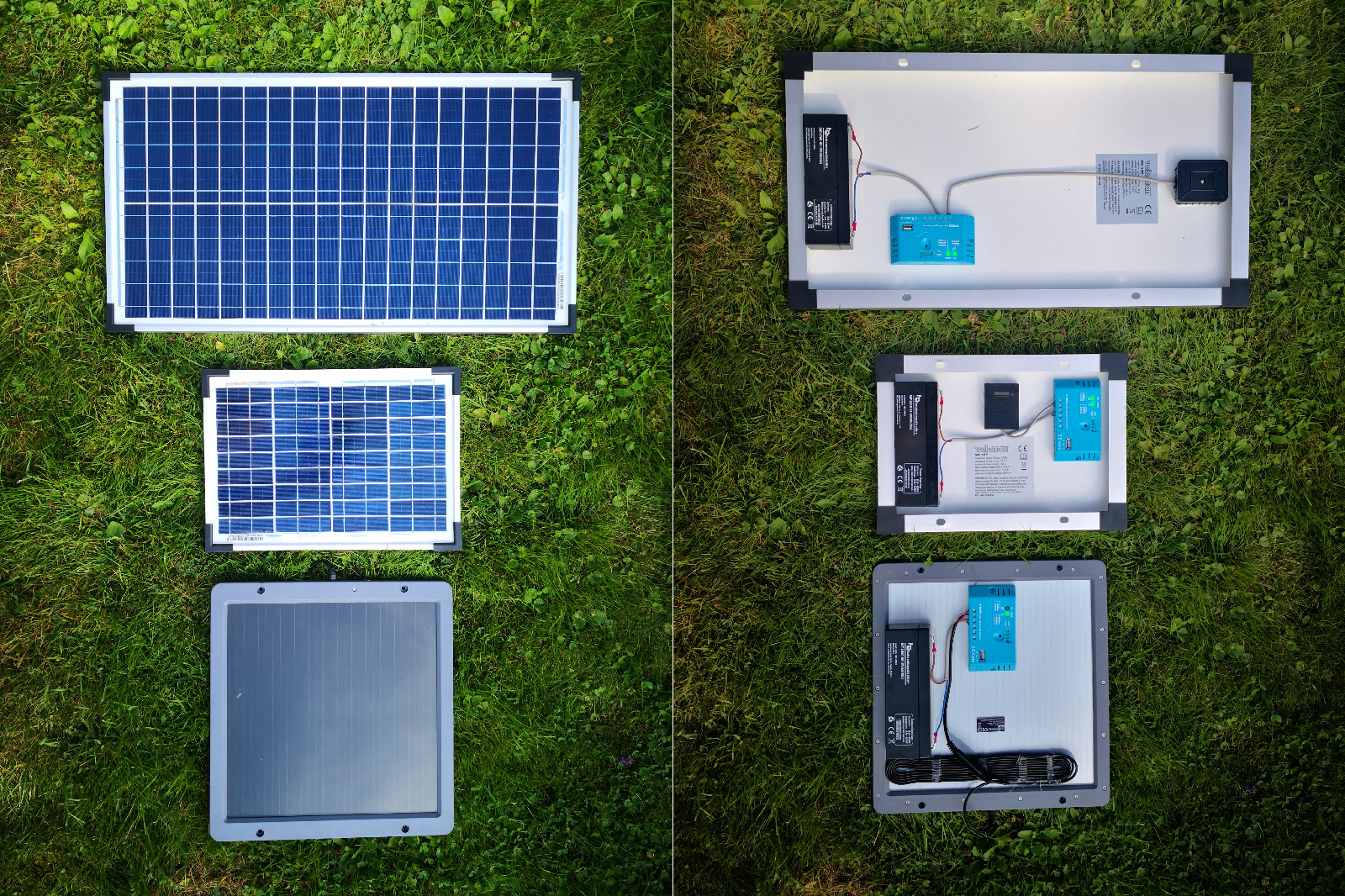 Solar panel setups
As can be seen in the picture above, the amorphous silicone panel with 5W output is bigger than the traditional Polycrystalline 10W panel. The 30W panel has the same battery, but the larger panel should in theory maintain the battery reasonably even if there is no direct sunlight for a few days. When I started this project, I was curious to see how far into the winter the 30W panel would keep working.
Test conditions
This is by no means an ideal test. It’s just me satisfying my own curiosity. My garden is not on the top of a hill with abundant sunlight. Instead it’s down in a small valley and there’s lots of trees to block the sunlight. In summer, we still get quite a bit of sun as the sun is high upon the sky. As fall comes, the leaves fall off the trees surrounding the garden, but it’s still not a lot of direct sunlight.
In winter, there’s only 3-4 hours where the sun could potentially hit the panels so positioning is crucial. This is just how it is when living in Oslo, Norway. Further north, it would be even less sunlight. In fact, parts of northern Norway do not have any sunlight at all for several months during winter. They make up for this in the summer as they’ll then have the opposite - days where the sun never sets.
As can be seen from the picture above, I’ve done nothing to protect the battery or charger. They’re just stuck to the back of the panels using a high quality dual side tape.
Test results
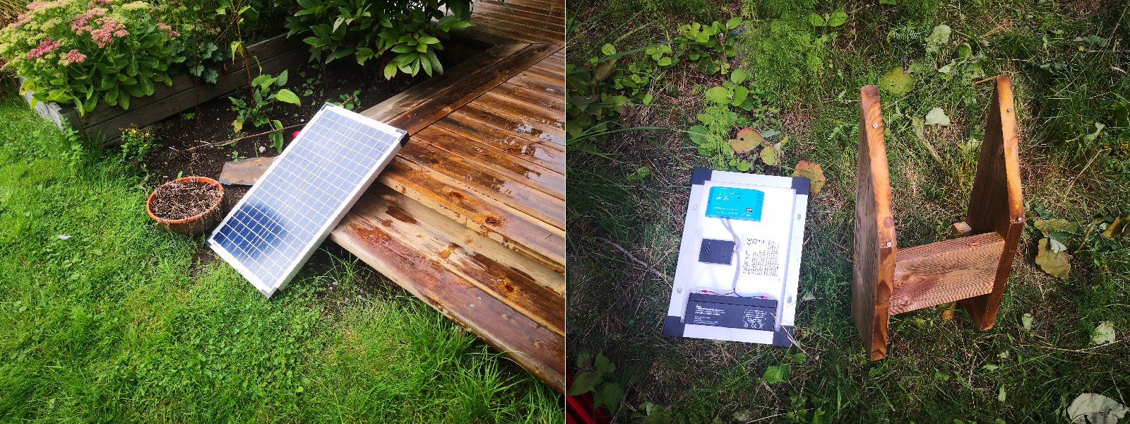
To test the different panels, I set them up at different locations to simulate different lighting conditions. I had no doubt that they would perform well if put in an ideal location, so to test a worst case scenario I opted to place them on the second floor shallow terrace, under the roof of my house and behind a fence. The fence covered the panels 50%. Here they hardly got any direct sunlight, so they should drain quickly. After two days of mostly grey and rainy weather, the Solar Charger didn’t have enough power to feed itself. This was the same for both panels.
After this, I moved the panels up above the fence. Still not very ideal in terms of direct sunlight, but they’ll at least catch a few rays in the evening. With this placement, the batteries charged somewhat, but as soon as there was a cloudy day, they’d drain. With this placement, the batteries lasted 5 days with no load other than the charger itself. This indicates that as long as there is some sunlight, the batteries will charge. Realistically though, this won’t cut it as you’ll easily get a week with little sun during a typical Norwegian summer.
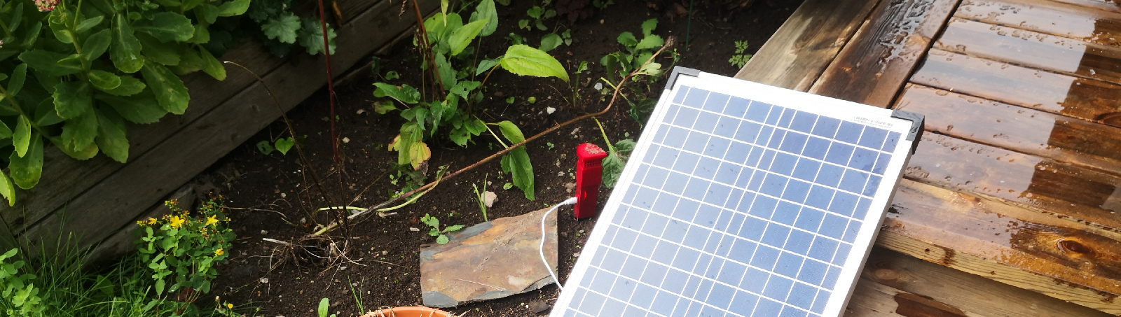
Next up I moved them down to the ground floor where they would get sun most of the day. I basically just tilted the panels slightly on the terrace as can be seen in this video. This provided enough sun that the battery was charged pretty much all summer. I had two HiGrow sensors running off the batteries and this held up until autumn approached. With more cloudy days and a constant drain of up to 130mA the sensors started dropping out more and more. When Autumn hit, only the 30W panel had enough power to drive anything and position and angle really became important.
Lessons learned & my plan ahead
Placement is everything for solar. Anything only partially blocking the panels will severely reduce the output, so next summer I’ll do some trimming of the tallest trees in the garden to ensure that I have power all summer. I’ve concluded that unless you make something very low power, 5-10W is not enough to run an IoT device and not even a poorly optimised PWM charger. 30W can work if you’re good at conserving power, but it won’t last a Scandinavian winter. I’ve now purchased a 50W and a 125W polycrystalline panel for further testing this winter.
In general, I’ve learned that you cannot expect more than about 30% of the theoretical maximum output from a panel, so a 30W will realistically only give you 10W unless the panel is placed on a solar tracking device and always pointing exactly at the sun. If you base your calculations around this number, you should be able to make something that’ll be able to stay online.
The PWM chargers I’ve used in this test leave a lot to be desired. The only way you can monitor them is to look at the LED’s at the back. These LED’s are always on, so alone they do likely draw 10-15mA each. Worst case - with a fully charged battery - up to 6 LED’s will be on, pulling an extra 60-90mA. Not ideal in any way. I’ve done quite a bit of research and small scale solar chargers in general are quite bad. They have pretty much no relevant information to provide you as an IoT person, so I started looking at making my own MPPT solar charger. These are much more efficient than the traditional PWM based chargers out there and the electronics does not seem too intimidating.
One problem about rolling this yourself is that you only have that much time and looking around I found this absolutely excellent MPPT project on Hackaday. Just as I was reading up on it, the project creator Dan Julio launched his CrowdSupply campaign. This board has everything I’ve wanted in a solar charger and I didn’t have to spend all summer creating, testing and writing software so I went for it. It will report realtime charge and battery voltage and has a solid host of features that would take me months to do myself so at $80 for two boards, this was a no-brainer in my book. The project is Open Source, so I’ll be able to do any tweaks I want. The board will handle the charging and then I can focus my efforts on making a low power IoT board that piggybacks it.
The drawback is obviously that I can’t get it right away, but with some luck I can start playing with it just before Christmas? Fingers crossed!