Implementing Over The Air (OTA) updates with ESP32
14 August 2024 at 9:59 am
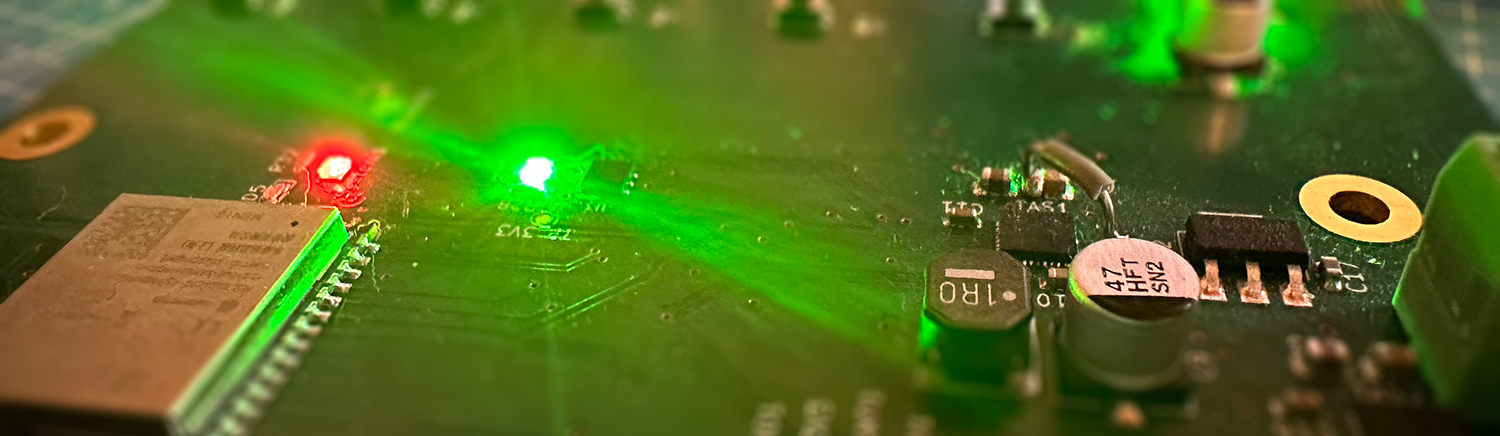
I'm currently working on a customer project where we have a series of IoT devices that will be spread across the country, making it impossible to update them manually. My former IoT projects have been wifi only and they've had pre-made update mechanisms. This project is based around the ESP32 S3 and here's a summary of the things I've learned that may be a good primer for anyone getting into OTA with Espressif.
To explain OTA briefly - you'll need to set up a software that can feed a firmware file to the ESP32 device. The ESP will save the data to one of two places in the Flash memory. Once the entire file is sent, the hash of the file is compared to what was sent to ensure that the file is valid. If it's valid, we'll set the ESP to boot from the new firmware and restart.
Easy start
First off - if you are using the Arduino IDE or ESP-IDF, you can use pre-build setups. Just select one of the available partition options that are not “minimal” or “No OTA” in the menu.
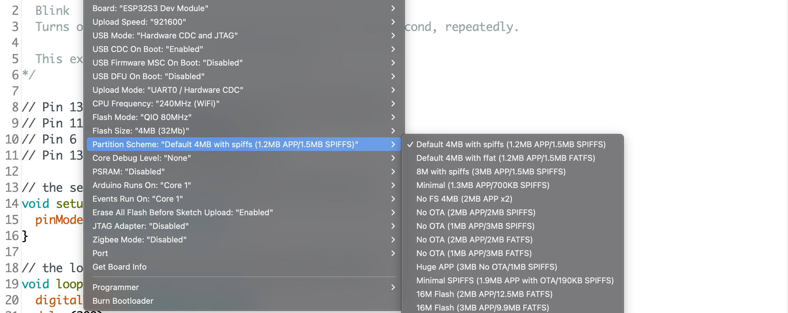
Combine this with one of the examples and you have the basics ready. The OTA tutorial of Andreas Spiess is a great place to start for casual development using only wifi. For hobby purposes, that's often all you need.
This is also a great place to start if you want to study how the Espressif Update system works. Digging into the file that controls the OTA process, you can see it's linking the file “Update.h”. This is the file that does the grunt work. In most professional setups, you'll want to use “Update.h” or to implement your own version of it.
I'm using custom hardware over both wifi and cellular, so I need a more custom setup than the Arduino IDE can offer. I'm using the PlatformIO IDE / VScode in general, so the below is using that as a basis.
Setting up a project for Over The Air (OTA) Updates
To use OTA, you'll need to set up a partition table that has room for at least two OTA partitions. If you're using the Arduino IDE, you can select from one of the many predefined setups. For most playing around and testing, that will cover what you want.
If you have specific needs, you can create your own partitioning scheme in a CSV file like this:
# Name,   Type, SubType, Offset,  Size, Flags
nvs,      data, nvs,  0x9000,  20K,
otadata,  data, ota,     56K,  8K,
factory,  app,  factory, 64K,  1M,
app0,     app,  ota_0,      ,  1M,
app1,     app,  ota_1,      ,  1M,
Each of these entries is a region of flash memory that is set aside for a purpose - just as a partition on a harddisk would work. Just as on a harddrive, it's somewhat tricky to change this later so be sure to leave enough space for your app. A good rule of thumb can be to use the double of what you think your final App will be.
This table can either use HEX addresses directly or just chunks of memory (that will then be mapped out to HEX addresses as above). How much memory to use is dictated by which chip/module you're using (2, 4, 8 or 16Mb flash). You can find more details on setting up the partitions here, but you have quite a bit of flexibility.
When you initially Flash the device via USB/Serial, this firmware will go into the “factory” partition of the Flash. When you later use OTA to update the firmware, the first firmware uploaded will go into the “ota_0” partition. The next uploaded OTA firmware, will go into the “ota_1” partition and from then on, the ESP will toggle between these two. Optionally, you can add more than two OTA partitions, but two is the minimum. The OTA update will never touch the “factory” partition. By selecting to boot from this, you can always revert the device to a “known good” firmware if something goes wrong with OTA.
Note that to use OTA, you MUST have at least 2 OTA partitions as per the OTA documentation. The reason is that once you flash an OTA app to ota_0 - where will you store the next OTA update? The update would crash if you wrote it to the same flash memory as the running code. The ESP will automatically toggle/cycle between the two (or more) OTA partitions, so you always have a dedicated space to receive the next update.
To use this custom partition table in a tool like PlatformIO, drop it in the root folder of your project and link it in the platformio.ini file like this:
board_build.partitions = custom_board_4MB.csv
board_upload.flash_size = 4MB
When I make IoT hardware for customers, I'll typically also make a custom board in PlatformIO to get PIN mappings and everything else so it's easy to work with.
Performing the update
You'll set up an application that can send the firmware to the device in chunks. I have a custom React application that I'll start on my computer when I make an update. This could easily be deployed to a server as well, but I prefer this software not to be online at all times for security reasons. This keeps the update mechanism hidden and makes it harder for intruders to figure out how my update system works. I also don't have to update very often, so no need for it to be on a server.
Before the first chunk is sent, we'll also send an MD5 hash to verify against once finished. Each chunk received is written to the selected OTA partition. The Updater is made to be very flexible, so the size of the chunks are up to you. Some solutions will use huge chunks to perform the update as quickly as possible. In my case, I want the device to function as normal while it's updating. By keeping the chunks quite small, the processing is minimal and screen and realtime audio can play despite an update happening in the background.
If an update stops for any reason, nothing happens. You can just restart it. As long as the firmware does not have errors that prevent it from reconnecting, you should be fine. There is only one point in the update process that is critical and that's when selecting what partition to boot from. Getting a power outage at just this millisecond in the process could in theory cause problems, but Espressif has made a very solid process overall so it's not likely to go wrong.
Switching between partitions
At this point, you have OTA working. Every time you upload new firmware, it's saved on the other OTA partition and after verifying using the MD5 hash, it then boots to run the new firmware.
But what do you do if it's not working as intended? As mentioned, you can always revert back to factory firmware. This can be done in many ways and a common way is to implement a physical “reset”-button that you hold down for a prolonged time. How long? Long enough that it won't happen by accident. Next you'll want to import the file named "esp_ota_ops.h".
This ESP-IDF file holds code to select the partition to boot from, as well as other useful methods for selecting the right partition. You will find many examples online on how to do this, but the core is that you locate the “factory” partition in memory and then set this to be what the device should boot from. You can also use similar code to boot from any other partition as needed.
Security
I recommend setting any commercial project up using Transport Level Security (TLS). As the name says - this moves security to the transport layer of your application and it's the most standard way to protect your app. You should also add security layers to any servers you talk to. I typically prefer to use a middle layer such as MQTT/AMQP since that is transport agnostic. I can use this via both wifi, subGhz and cellular with only a thin abstraction layer in my app. The App itself only talks a single protocol over whatever security that has implemented.
How much security is enough? It's hard to say, but when I set up the server I was accidentally watching the server logs and within one hour of the server going online, a scanner started mapping out my entire backend server - brute force - by first trying every common URL (such as “wp-admin” for Wordpress), then starting a dictionary scan and then scanning systematically like this.
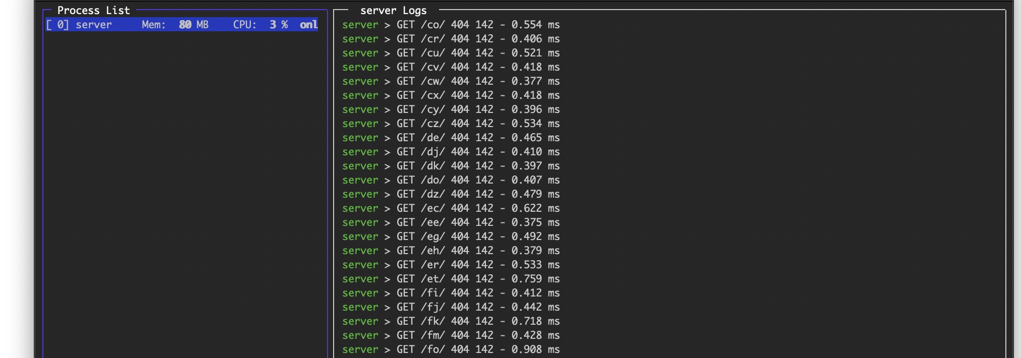
I stopped this scanning by setting a password for any access to the server, but you're only as safe as your server software…
Gotcha's
Once firmware have been uploaded, you can upload as much as you want via USB, but the device will always execute the OTA firmware. The brute-force method to solve this is of course just to Erase the Flash memory. The elegant way to do this is to revert to booting from the factory firmware (as explained above).
Note: If you're reading this to undestand the OTA process better and there's something I have not covered, feel free to contact me to ask me to update the article?