Implementing USB Type C and USB 3.1
27 April 2020 at 3:10 pm
For a Client project, I recently implemented a USB 3.1 (Gen 1) hub with Type C cable input & output. It was quite a learning process as USB 3.1 is kind of finicky, but it also made me keen on learning more. From now on, I’ve decided to use USB Type C in all the electronics I create so I need to explore alternatives. If done right, you can get Type C at near the same price as USB Micro. If you want to experiment with USB C, be sure to check the PCB’s end of this post.
If you’re just starting out with USB Type C, check out this small primer on the different USB standards. My main reason for opting for USB C on all projects is that it’s about time.
What USB type C offers
USB Type C (Type C or USB C for short) is just the physical plug, just like USB A, USB B, USB Micro or USB Mini. Type C is small enough to be used in a mobile phone, but solid enough to withstand many thousand mating cycles. Impossible to insert the wrong way, you always plug it in on first try. The idea is that it will eventually replace all the former plugs and you can use a Type C plug with any of the current USB standards. Generally, a higher version number in the list of USB standards (2.0, 3.0, 3.1, 3.2), offer faster transfer speeds. Depending on how you supply power to your device, you may also source up to 100W (5A @ 20V) of power to your project.
One plug to end them all? Sounds great, but why would you use a Type C connector and cable if your project only needs a few milliamps of power or only sends a tiny amount of data at slow speeds? The main reason should be to future-proof it. Given that Apple and all mobile phone vendors on Android now use a Type C connector, it is no longer a drawback if your device has one too. A whole new generation of users are now entering adult life. My 15 year old daughter only has devices that use USB C. Her Android phone, headphones and iPad all use USB C, so she has plenty of these cables. Not to mention - some weeks ago the EU voted to force mobile phone suppliers to use it.
If you are making something that should last for more than a few years, it is soon more likely that the customer will have a Type C cable available than other variants. It offers many new options, in addition to full backward compatibility with USB 2.0 devices that are up to 20 years old.
Getting ready for experimenting
I’ve made 3 simple breakout PCB’s for playing with USB Type C: One for just power, one for USB 2.0 and one for USB 3.1 (with all 24 pins). I could have made one for USB 3.0 too, but I see no reason not to just use 3.1 right away. The power-PCB can be hand soldered, but the others have such a fine pitch that I’d recommend using a stencil and reflow oven.
Kicad comes with three USB Type C footprints and all but one of these are obsolete. The parts are also somewhat expensive at $2.5 or more in low volume. The three boards I’ve made will test three new footprints based on low price alternatives and will allow me to easily add USB C to new Kicad projects. They’ll also come in handy for experimenting and testing USB C devices. Each of the boards can be used for one of the cases below.
Case 1: Just power things
Part to test: TYPE-C-31-M-17 ($0.22@1,$0.14@100pcs)
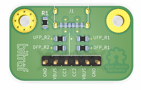
If you just want power for your project, there are very cheap Type C connectors available ($0.14 @ 100 pcs) that can withstand 10.000 mating cycles. This is from a Korean manufacturer and if the quality is what it promises, this will be a great addition to any device. What if you need more power than USB 2.0 / 3.0 can offer by default? The CC1 and CC2 pins on the USB Type C plug are used announce how much power you can expect from a Host device. On the PCB, I’ve added solder pads so I can easily experiment with this by soldering resistors connected to the CC1 & CC2 pins.
If you are making a USB port on a Host device (something that is a source of power for other devices), it’s called a Downstream Facing Port (DFP). A hub or a PC is a typical DFP. It supplies power to the things connected to it. By pulling the CC1 and CC2 pins up to either 5V or 3.3V using these resistors, you can tell that your DFP offers the default 500/900mA, 1500mA or 3000mA of power at 5V. This means that by just soldering some resistors, you can let other devices consume up to 15W (3A * 5V). You can find the list of resistors to use in section 3.1 of this document.
If you are making a Device that needs power, it’s called an Upstream Facing Port (UFP). Configuring a UFP is quite simple. Just use a 5.1kΩ resistor to pull down CC1 and CC2 to GND. That will make the Host see this as a device. This board will let me test if this is sufficient to supply power.
According to the USB Battery Charging v1.2 spec, you’ll only get a tiny amount of current if you do nothing other than connect GND and VBAT. By default, USB 3.1 Hosts should only offer up to 100mA to a device unless there is a connection of the USB 2.0 data lines. However, if you place a 200 ohm resistor between the D+ and D- pins, you’ll be able to draw power up to the limit of the Host device. This resistor produces a (mild) short that tells the Host that there is no need to try to talk to the device. Such a device is called a Dedicated Charging Port (DCP). I’m not 100% certain that the shorting of D+/- is required if you set CC1 and CC2, but this board will let me test that out.
So now the CC1 and CC2 pins are connected to resistors, but how do you read them? They could be connected to the analog inputs of a Microcontroller, but it’s quite common to just use a dedicated IC to do this. I’ll get back to this under Case 3.
Case 2: USB 2.0
Part to test: TYPE-C-31-M-12 (($0.38@1,$0.24@100pcs)
This is the version I’ll likely use the most of. This is what you’ll want if you want to hook up the builtin USB 2.0 controller in an STM32 based microcontrollers or to the serial interface IC of an Arduino, ESP32 or similar.
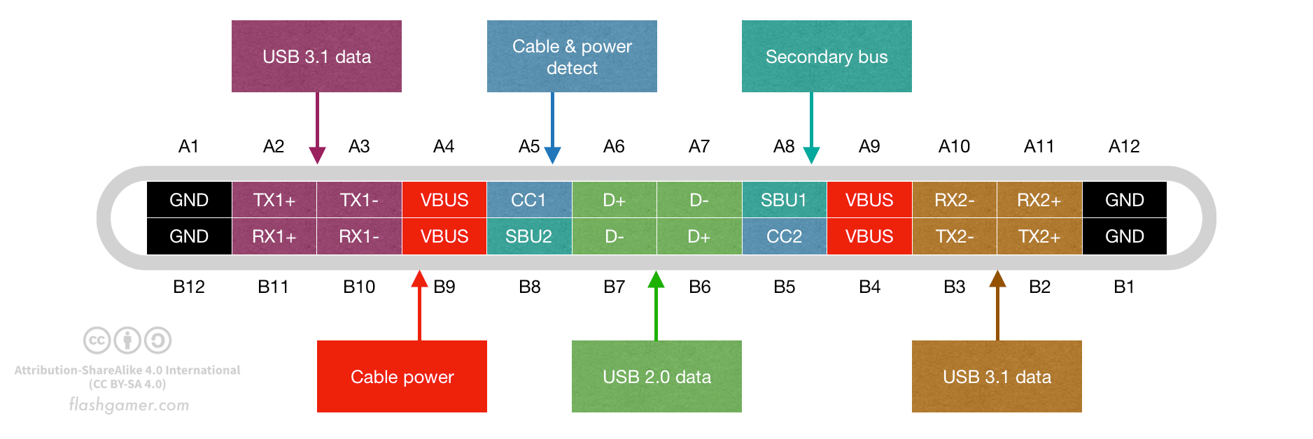
To make a USB 2.0 connection using a Type C plug, we’ll just need to hook up GND, VBUS, D+, D-, CC1 and CC2. On these connectors, the SBU1 and SBU2 pins are often also present. These pins are only used for Alternate Mode, so I’m unsure why they are in the connector at all. I would guess it’s just because they are opposing pins to the CC-pins, but I really do no know.
USB 2.0 has two channels to transfer data (D+ & D-). In the USB Type C plug, these are in the middle of the plug and you if you rotate the cable, you’ll just use the other connections. Thanks to this, it’s very cost efficient to make USB 2.0 devices with USB Type C connectors.
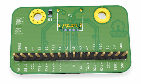
Case 3: USB 3.1 device
Parts to test:
- U262-241N-4BV60 ($0.47@1,$0.30@100pcs)
- TYPE-C-31-M-04 ($1.26@1,$0.82@100pcs)
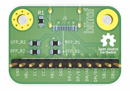
The third board I’ve made, exposes all the 24 pins in the USB Type C plug. Making a USB 3.1 device is not as straightforward as the previous two examples. USB 3.1 has a lot of capabilities such as a cable that can be plugged any way, SuperSpeed transfer, Power Delivery, Alternate Modes, Battery charging and more. It’s up to you to figure out what features in the list you need, but they all require precise PCB layout and custom IC’s. The fact that you can plug a USB C cable in both ways comes at a price.
Getting USB 3.1 speeds
To deliver SuperSpeed signals, you have to physically match the length of the RX/TX lines down to less than a millimeter. To get this working, you’ll need to use “wiggle lines” or Differential Track Tuning as it’s called in Kicad. The data lines should be as short as possible and not have any “interruptions” such as vias or trace lines straying off from the main trace. It should have a ground plane underneath, and it should preferably have ground around it too.
The PCB layout must follow strict rules for impedance, so you can’t just ship this off to china and hope for the best. The trace width & spacing of all data lines must be calculated carefully to meed intended impedance values. Good vendors like Eurocircuits will offer a calculator and guidelines for getting this right. This also means that you can’t use the cheapest pricing either and it might reduce the number of vendors you can use.
Getting this to work 100% can be really tricky and it took me 3 attempts to get USB SuperSpeed right in my client project. It’ll go faster the next time, I’m sure but it’s worth taking into account that you may need more than just one take at this. While I have designed the USB 3.1 breakout according to best practices, it will likely never deliver any SuperSpeed+ signals if you plug it into a breadboard using jumper wires. It is still useful for prototyping as most parts that you’d like to test with it will also fall back to USB 2.0 if highspeed fails.
Configuration Channel Logic, Port Control and MUX
To send and receive data, we’ll need to first detect the orientation of the cable and then use an IC that can switch what RX/TX pair we should listen to and send from. It might be tempting to think that you could just connect up and read out all these lines just as for USB 2.0, but that won’t work. The cable can be normal or flipped at either ends of the cable, so that gives you 4 possible positions. You’ll need to read only the actively driven channels. Non-active wires would work like an antenna, so it would disturb the highspeed signals.
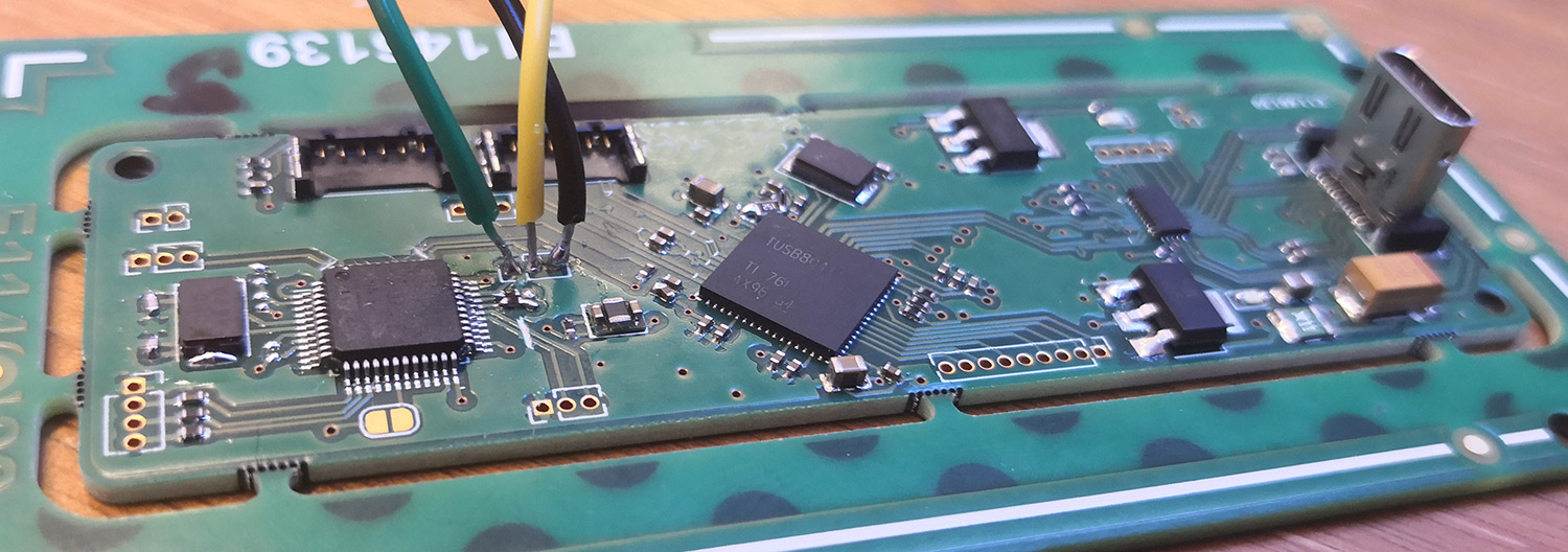
There are IC’s that can do both these things in one. I’ve formerly used the excellent and fully featured TI HD3SS3220 ($1.22@1, $0.78@100pcs), but I’d like to see if there are lower price alternatives. This part does cable detection, CC-configuration, cable orientation, it switches the data lines and offers some basic builtin ESD protection. The fine pitch of this part (0.4mm between the VQFN pins) also increase the price of each PCB a bit so it would be good to have an alternative in projects where space isn’t too crucial.
There are many IC’s for both monitoring and setting the CC1 and CC2 pins on a USB Type C connection. One of the more popular ones are TUSB320 from Texas Instruments. This is an I2C device that can detect 5V power on the VBUS lines, It can tell you the orientation of the cable (Normal or Flipped) and it can tell other devices if your device is a Host (DFP), a Device (UFP) or both (Dual Role Port, DRP).
These IC’s come in several versions. Some are made for chargers, so they’ll only have cable detection and power negotiation, but these may also have some battery charging circuitry. An example of this is VIA Lab’s VP223. It’s nicely priced ($0.51@1, $0.34@100pcs), but the datasheet is painfully short so the nice price and the EOL part status is a no-go.
TI has the TUSB320 series. Some of these are priced quite low at LCSC such as TUSB320HAIRWBR ($0.49@1, $0.31@100pcs) and they are pin compatible with other ICs in the series, so it won’t hurt you if this specific variant goes obsolete. By itself, it can only detect power on the CC pins and cable attachment. To supply power (PD) it’ll need a separate IC for that and to do USB 3.X data, it will need a switch/mux.
On Semiconductor has several interesting parts and FUSB302 is well priced. FUSB302T ($1.09@1, $0.70@100pcs) is the latest iteration. It can do less, so it requires a switch like the FUSB340 ($0.94@1, $0.61@100pcs), but overall it’s not a bad combo. The FUSB302UCX variant comes in a crazy tiny package of just 1.21x1.26mm so if size matters it can be a good part.
ST also has some USB C parts, but I can’t seem to find a USB MUX? They have the logic controllers STUSB1600 for dual role ports ($1.57@1, $1.02@100pcs) and STUSB4500L ($1.65@1, $1.11@100pcs) for device. Both are available as QFN with 0.50 mm pitch, but the STUSB4500L is also available as a smaller BGA version. These target consumer devices like printers, camcorders, cameras, toys, POS-devices, lighting, e-cigarettes, IoT devices and more, so it seems like a correct choice. One would have to use a switch from someone else like for instance PTN36043 from NXP?
There’s so many choices, but according to my research, none are as complete and simple to use as the HD3SS3220. The more I look at the alternatives, the better I like this IC. I guess I’ll stick to that for now, since all that it’s missing is a separate PD controller but if my project requires more than 15W @ 5V. I wish they also offered it in a 0.5mm QFN though.
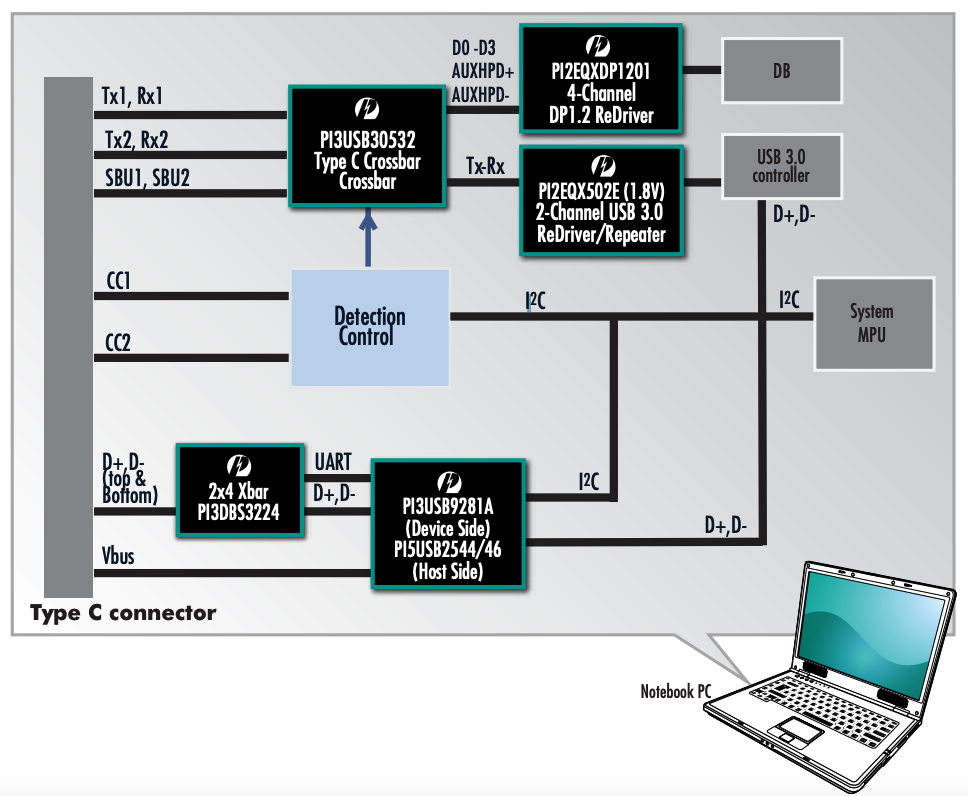
ESD protection of the data lines is whole other chapter. TI offers the TPD4EUSB30 and ST the TCPP01-M12 that can help with that, but there’s so many things to consider that it really depends on the application. Just have a look at how Diodes inc explain what IC’s that go into adding Type C support to a PC. When I look at that, I’m kind of glad that I only make small devices for getting all those IC’s to play nice while maintaining data integrity is certainly a massive task!
USB Type C breakouts download
If you want to play around with my breakout boards for lower priced Type C connectors, you can find Kicad files each of the boards in my Github repository for USB Type C. All files are Open Hardware, so enjoy them freely but use at your own risk. I’m still waiting for my first batch of boards based on these files. I’ll post any updates to Github.