USB Type C (and USB 2.0, 3.0, 3.1 & 3.2)
24 April 2020 at 4:33 pm
Up until 2019, I only used USB 2.0 in my circuit designs, but for a customer project I had to implement a USB 3.1 Superspeed device using a Type C connector. Looking at the standards, it’s not hard to implement a Type C interface, but it’s harder to get Superspeed to work reliably. Here’s my notes in the form of a short USB primer for anyone adding USB Type C to their projects.
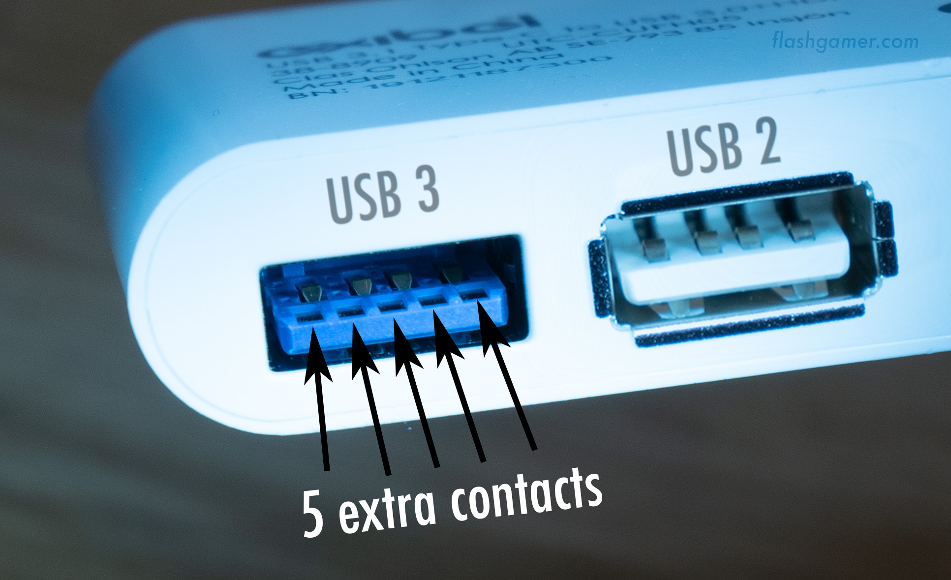
In the picture above, you can see that the USB 2.0 port has only 4 metal pins inside. The (typically) Blue USB 3.0 port on the left has 5 extra contacts in front of the normal 4 pins, giving this port a total of 9 connections. These extra pins allow the higher speeds and extra power transfer.
Below is the pins of a USB C port on a master device such as your computer or a hub:
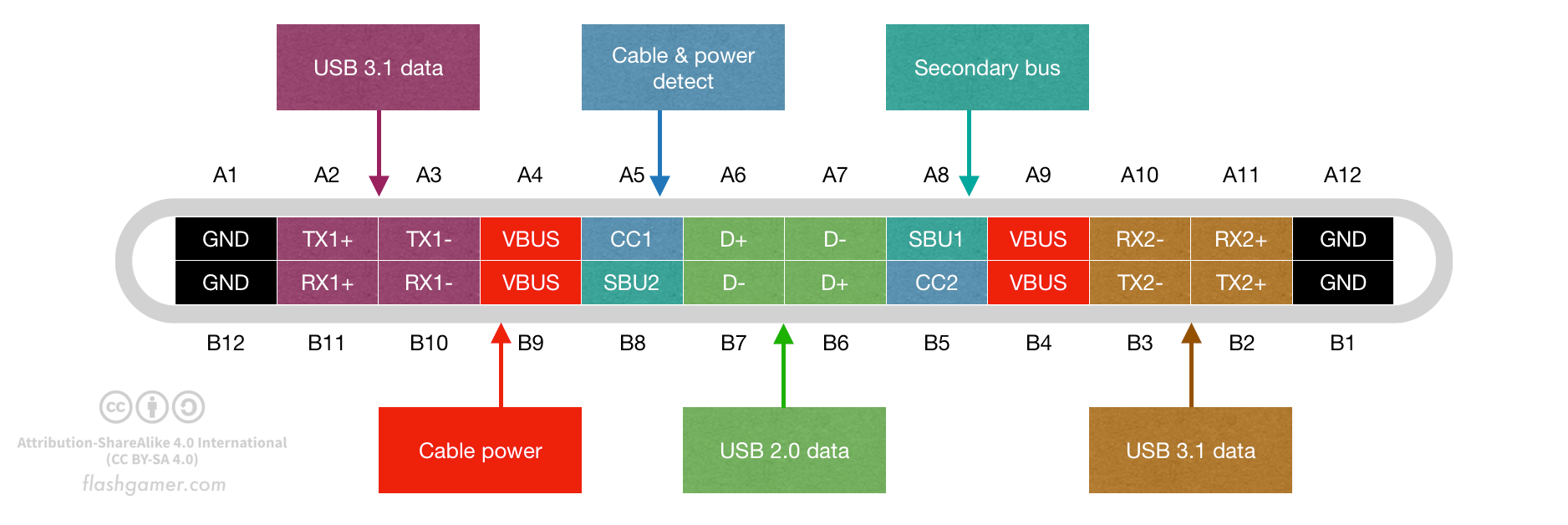
As you can see, there’s 24 pins in the receptacle, but you don’t need to use all of them. If you need to supply power to something simple like a microcontroller and some low power sensors, you can just tap into the GND and VBUS pins. This will give you 500mA of power if you plug the other end of the cable into an old machine with USB 2.0, or up to 900mA. if you plug it into a USB 3.X port using a USB 3 cable. For many things, this is all you need. By setting up resistors on the CC-lines and detecting capabilities at the Host, you may also be able to request both 1500mA and 3000mA.
These current limits are set in the USB specifications. USB 2.0 dictates that no device should be able to consume more than 500mA, so the Host should not offer more current than this. You can implement this using a PTC or similar device. This will protect from shorted cables and other issues. USB 3.0 extends this to 900mA for all ports. To supply more power, you need more copper in your cable. This is solved by increasing the number from pins in the USB connector from 4 to 9.
To implement a USB 2.0 interface on a Type C connection, just add D+ & D- to the power connections. Quite easy!
To implement a USB 3.0 interface, connect the Type C connector as you would for USB 3.1 according to the drawing above. The orientation of the cable will decide what RX/TX pins are being used.
To implement USB 3.1, check my article on how to do this. Given the higher speeds and options available, doing a 3.1 device can be quite a bit more complicated than for the former versions. You’ll use the CC pins to detect cable orientation, how much power the Host (PC, Hub or similar) can supply and much more.
The table below lists the raw facts for what you can get with each of the standards.
| Version | Name | Transfer speed | Power | Number of Pins |
|---|---|---|---|---|
| USB 1.0 | Low or Full speed | 1.5 MB/sec | 0.5A / 2.5W | 4 (GND, D+, D-, 5V) |
| USB 2.0 | High speed | 35-40 MB/sec | 0.5A / 2.5W | 4 (GND, D+, D-, 5V) |
| USB 3.0 | SuperSpeed | 300 MB/sec | 0.9A / 4.5W | 9 (GND, D+, D-, 5V, RX+, RX-, TX+, TX-, GND drain) |
| USB 3.1 | SuperSpeed+ | 1200 MB/sec | 0.9A, 1.5A or 3A, up to 15W * | 24 |
| USB 3.2 | SuperSpeed+ | 2400 MB/sec | 0.9A, 1.5A or 3A, up to 15W * | 24 |
| USB 4.0 ** | SuperSpeed+ | 4800 MB/sec | 0.9A, 1.5A or 3A, up to 15W * | 24 |
*) Type C systems will supply 5V as default, but if both the Host and Device are using USB Power Delivery (PD), you can go as high as 12V @ 1.5A (18W), 12V @ 3A (36W), 12V @5A (60W), 20V@3A (60W) or 20V @ 5A (100W)
**) USB 4.0 is just a specification for now, but the first hardware should arrive late 2020.
Keep in mind that while your device implements a USB Type C port, this does not mean that the other end of the connection will be a USB 3.1 port. A 2.0 device with a 3.0 cable, will give you only 2.0 speeds and power. To get the full benefit of standards above USB 2.0, you have to use a cable that has all the required wires. The connectors at both ends also have to support the same (or higher) number of pins. This may seem like a problem, but it really isn’t. The increasing amount of pins will make it easy for you to detect the connection at the other end. If a user plugs your device into a port that does not supply enough power for it to work properly, you can detect this and help the user plug into the correct type of port.
Actually achieving the high speeds promised in the USB 3.2 spec will require very careful PCB layout and high quality cables.
The USB naming mess
To confuse things, USB-IF is now calling USB 3.0 for USB 3.1 Gen 1 and USB 3.1 for USB 3.1 Gen 2. This is probably a severe case of technologists not understanding that the world does not revolve around USB for most people. Its easy for them to remember what “Gen” goes with what USB version since they work with it every day. Try to tell my mom, or even my tech savvy father to go get a “USB 3.1 Gen 2” cable and he’ll be lost. It’s terrible to see this explanation from memory card vendor Kingston, where they have to use a good part of the article to tidy up this naming mess.
Let’s just keep the old names of USB 2.0, USB 3.0 and USB 3.1? They tell us the physical format and speeds - without added confusion.
Detecting a connection
By just measuring the voltage on the CC1 and CC2 pins, you can know if anything is connected. You can also detect if the cable is flipped and what type of device is connected at the other end (Host or Device). Microchip has a nice explanation of how to read CC1 & CC2 here.
UFP, DFP or DRP?
If you are making a Host device (something that is a source of power for other devices), it’s called a Downstream Facing Port (DFP). A hub or a PC is a typical DFP. If you are making a Device (microcontroller, lightsource, motor or any other device) that needs power, it’s called an Upstream Facing Port (UFP). If your device can be both things, it may also be a Dual Role Port (DRP).
Power delivery (PD)
If you have a modern computer, it’s very likely that it has USB C for charging. Using PD, certain USB C connectors can transfer up to 5A @ 20V, providing up to 100W. I have no need for this much power in any of my projects for now, but it impresses me that it’s even possible given how thin the USB C cables are. Designing electronics to support PD has apparently been painful for early adopters, but it’s now getting easier with the second generation of IC’s. Due to this, it’s not a given that you can use any Type C charger for your computer, but expect this to get better over time.
Alternate modes
Not only can you use a Type C connector for USB. It can also replace your HDMI cable and Thunderbolt. These will “negotiate” between Host and Device over the 24-pin cable to check if it’s ok to use the USB port for other things. This will obviously require a circuit for the capabilities detection and if that goes well - the switching of lines to deliver a different signal on both ends of the cable.
Powered cables
One of the CC pins can also supply up to 1W power for special cables. This requires negotiation between the Host and Device so that not both try to power the cable.
Battery charging
USB 3.1 can also be used for battery chargers without any data capabilities. If D+ and D- does not have a connection at all, the current will be limited to just 100mA, but implementing a charger is as easy as shorting the USB 2.0 data pins pins with a 200 ohm resistor. This will allow more than 100mA to be output.