Making a Blinky cube
17 February 2012 at 2:03 pm
Inspired by various LED cube projects, I wanted to see how long it would take to prototype a small interactive toy. The basic idea is to make a plastic cube that displays beautifully diffused light and uses a simple way to turn on and off. Tapping the cube with a finger could be a good way to do this and it also makes it possible to start different “color cycle programs”.
Making the cube
My friend Jim at VariousArchitects (VA) has this really nice Makerbot standing around in our office. It would be a shame not to play with it a little? Maybe I could even find a complete cube on Thingiverse?
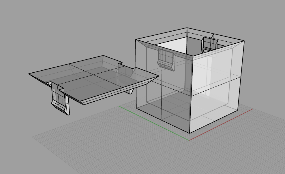
Turns out that nobody had done something similar, so I had to make the model myself. Through the years I’ve played with different 3D programs and lately I’ve used Modo a lot. After fiddling a while in both Modo and Sketchup, Kyrre @ VA suggested that I try Rhino. My friends @ pivot.no have always been big Rhino proponents and after some initial fiddling, I really started to like the software! Poor Kyrre had me pestering him with noob questions all eve, but the result turned out quite nicely?
Breadboarding the prototype circuit
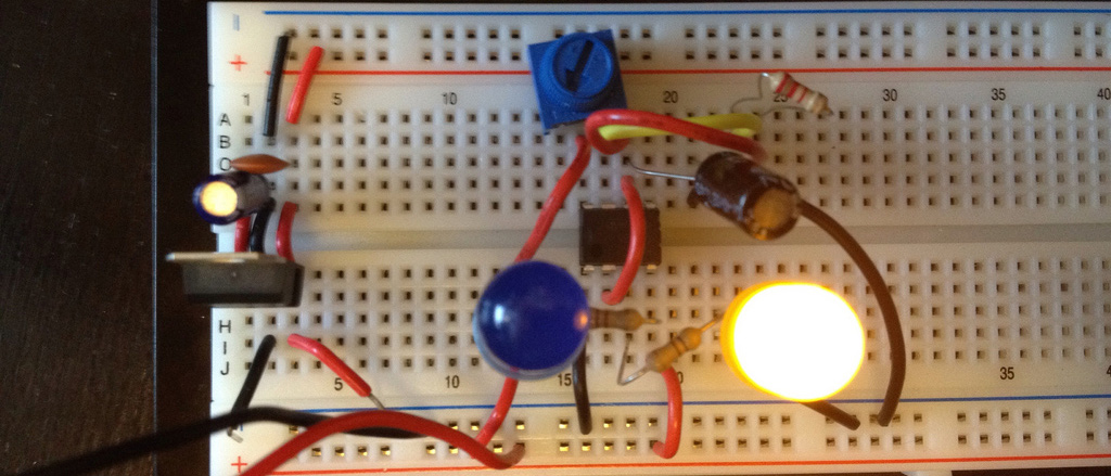
Next I needed to make a small test circuit to see that I could fit the electronics. The final version will use some sort of ATMEL chip, but since the hardware is still on it’s way (switch from Sparkfun and RGB LED’s from Evil Mad Science) I had to just throw something simple together that would show me how the LEDs worked with the materials.
Using my newly aquired knowledge about the 555 timer, I set up a small breadboard circuit that toggles two LEDs. I added a couple of 10k pot’s so I could change the blink speed. Looks like this would work fine?
Making it smaller
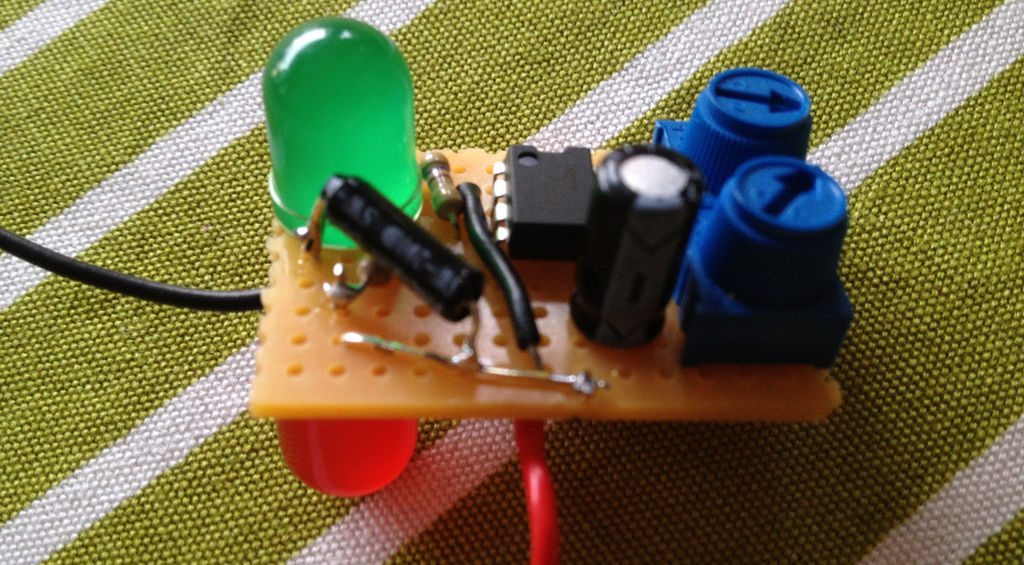
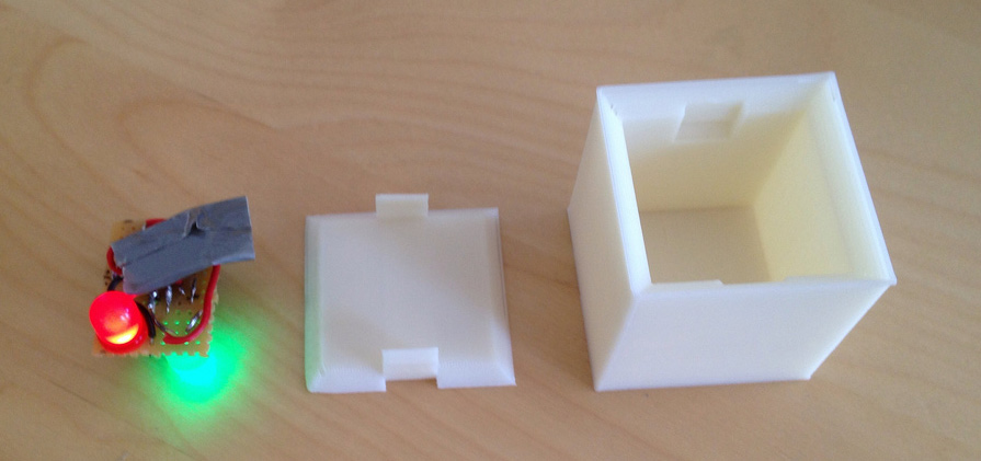
I can’t fit a breadboard in the cube, so I made a copy of the circuit on a little piece of perf-board that I thought would fit inside the cube. It took a couple hours to fit it all, but I only had one incorrect solder (the 555 was the wrong way, duhh) so it wasn’t all that bad. It also turned out quite small.
The blue dials are the pot’s that’ll adjust the blink-rate and the black tube on the top is a tiny switch that’ll turn the circuit on/off based on the physical orientation.
Putting the pieces together!
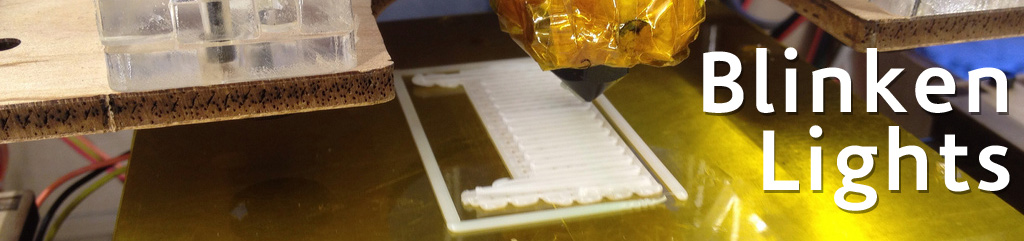
Kyrre had printed the bottom of the box that evening so when I came to the office the next day - all that was missing was the lid and some batteries for the circuit. While the lid printed, I mounted two 3V coin cell batteries together (the 555 needs at least 4.5 volts to run) using some Gaffa-tape and wait for the lid to finish printing. The lid required that the Makerbot made some “supports” - extra plastic that you remove when the print is finished. I’m amazed by how easily these supports came off and the pieces looked really good! Now it was time to fit it all together.
The result
Below you can see a video of the completed bits. The LEDs are not very visible inside the box while it’s daylight but they look lovely when it’s dark. The video is a little blurry since I just used my iPhone, but it shows the result quite well. Very happy with it given that it’s only taken about 1.5 days to get this far! Makes me feel comfortable taking the project to it’s next step - using RGB LEDs that can run different programs and turn on/off with just a tap.
Thanks a bunch to Kyrre for helping me with Rhino and the printing and to Jim for letting me play with his toy! I’ve also uploaded the 3D model to Thingiverse in case anyone needs something similar. I’ve also posted some more pictures of this on Flickr for anyone curious to see more.