Making a custom 3D printer controller
20 August 2014 at 8:12 am
While working on my new printer, I realised how ugly most reprap controllers are. All those I’ve seen use large SD cards & bulky oldskool LCD’s with really poor contrast and viewing angles. Why not use Micro SD & an OLED screen?
You can actually build your own custom controller using any combination of screen, SD reader and encoder, but I couldn’t find a good description of how to do it, so here it is. Setting it up with the Marlin firmware can however be a daunting task, so this article aims to document how I went about doing it.
I should start by saying that this is not “the right way” to do it, but I’m describing two of the many possible ways to do it. This description is for Marlin. If you are using Repetier on your printer, you may pick up some advice but the specifics will be different.
Picking the parts
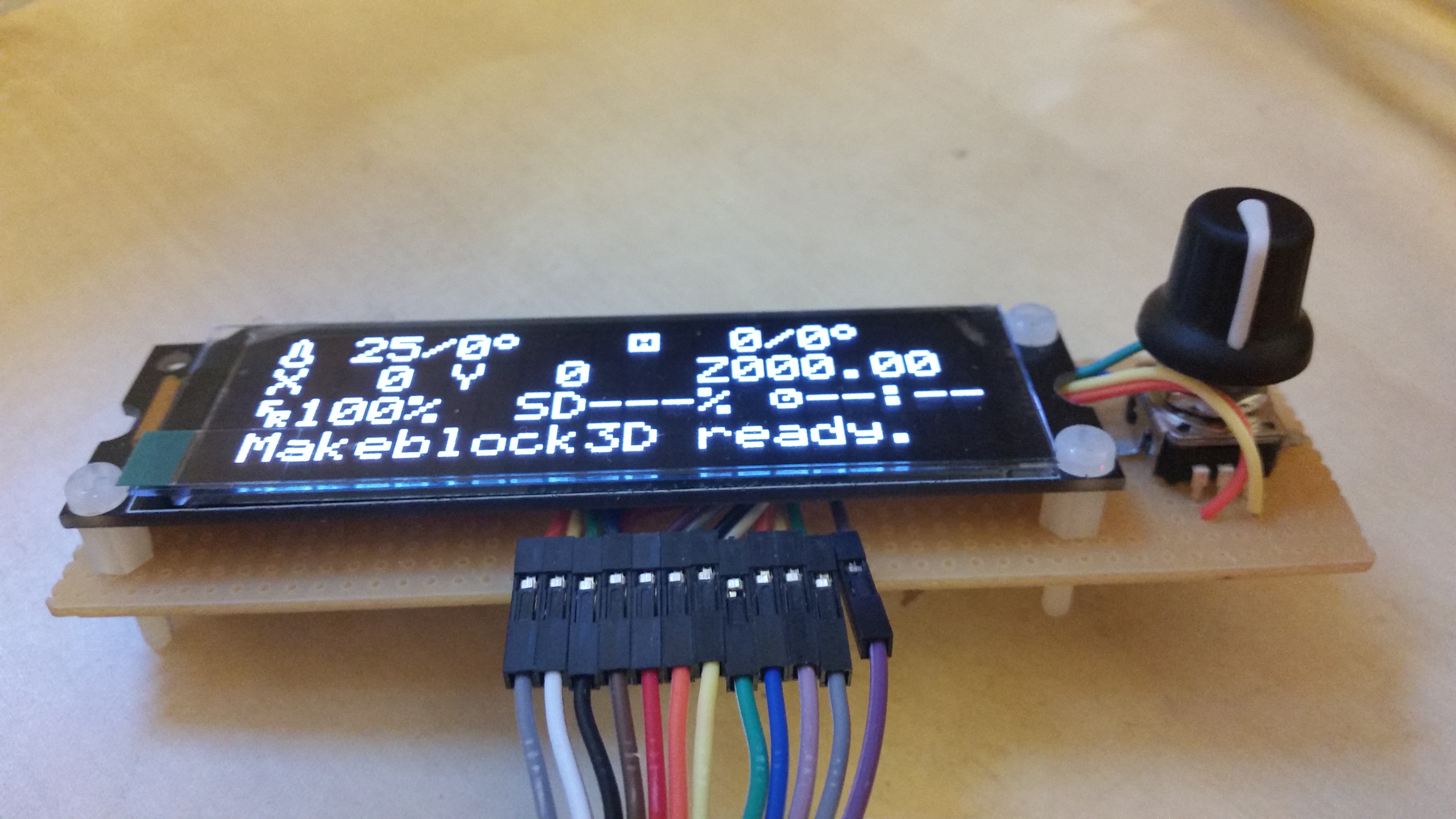
My biggest annoyance with the typical LCD’s used in these controllers is that if you’re not standing directly in front of it, you can’t really read the display. OLED displays use less energy than traditional LCD displays. They’re easily viewed from any angle and have a fantastic contrast. I settled on one from wide.hk that has the required 20 (wide) x 4 (height) character displays. These are less than 4mm (1/64 inch) thick and has good mounting holes. Cost $34.
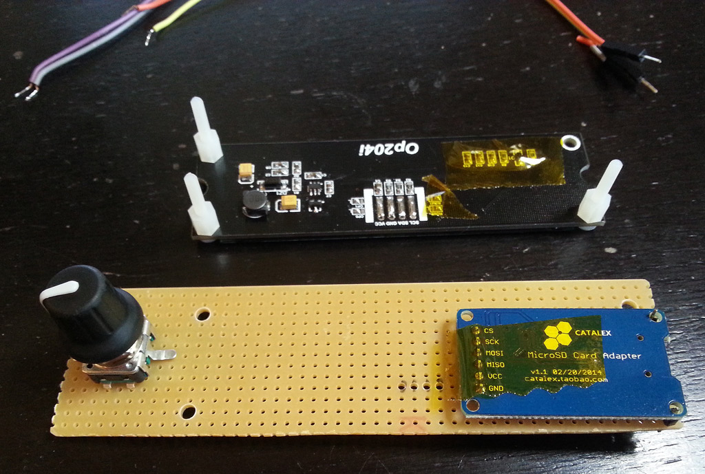
The SD card reader was something I had picked up from DX a long time ago A straight SD reader based on SPI. I got the encoder from Adafruit and I found a standard buzzer that was fairly small in a drawer. Pretty much any screen, SD reader, encoder and buzzer can be used.
Putting it together
Next is the fun part of figuring out how your controller should look! Grab your components and try to lay them out as smart as possible. Next you’ll need a way to connect them together. A standard perfboard cut to 125 x 35 mm (48 x 13 holes) is what I needed. Your needs will probably be different, but using perfboard makes it easier to lay things out and solder it once you know how you want stuff.
Another alternative is to design your own professional PCB using software like Fritzing. It would be a good first project, but it takes time to get the PCB produced. You can also add indicator LED’s and other custom components if you want to, but these will require you to add more custom code.
Finding your way around Marlin
I have a somewhat varied programming background, but C++ isn’t exactly my native tongue. That’s also my reason for doing projects like this - to learn more. I find the Marlin codebase a bit confusing. The root file is Marlin_main.cpp. The Arduino IDE will make a copy with .ino extension of this file when you start up the Arduino IDE.
At the top of this file is a load of #include statements. These are mostly files full of #define statements that are replaced by the compiler every time you hit “compile”, but they also contain methods that will reside in a “global/root” namespace. Take the fairly central file “stepper.h”. This is the header file for “stepper.cpp” that controls how the printer moves. None of the methods here belong to a class. They’re just “there”.
Coming from an object oriented programming background, I didn’t expect this. I guess there’s things/limitations such as dependency on interrupts that can force certain ways of doing things?
As far as I know, the first control panel for Marlin was added by fellow Ultimaker owner Bernhard Kubicek (thanks Bernhard!). After this, many others have hacked in support for their own panels. Over time, the codebase, and especially the config files, have become a little messy so it can be kind of hard to navigate.
Implementing your own screen
More or less any screen can be used, but it will require some modifications to the Marlin codebase. The first you’ll need is a small library that can print characters to your screen. Most screens will have standard functionality for this, so if you’re lucky you won’t need to write more than a little wrapper-code. In my case I received a barely functioning code snippet, so I had to do a little more work. You can find a ZIP-file with my Marlin implementation here.
These are the main functions that your screen class will need:
clear(); setCursor(row,col); write(uint8_t); createChar(uint8_t, uint8_t[]); // custom characters such as temp meter void printChar(char);
The clear() function obviously clears the screen and setCursor tells where the next character is placed on the screen. With these two and a print-command, you’ll have all you need. But wait - print() isn’t on the list? No, but if you look at my example OLedI2C.h class, almost at the top it says:
class OLedI2C : public Print
This means that the OLedI2C-class inherits all the functions in the print-class (Print.h) and expands on this. Without inheriting these methods, you’d have to write 18 functions to handle printing of all data types (uint8,uint16,char, bool, double and so on). The OLedI2C-class also “overwrites” the write-method. It changes the default behaviour of the Print-class to instead print to the screen we’re implementing.
There’s also two “special” commands in the list above. One creates custom characters (createChar) and the other prints it (printChar). These allows us the output graphical symbols for folder navigation, temperature, time and more. A standard “Character LCD” will typically have up to 8 slots for creating such symbols. If you’re using a “Graphical LCD”, you can create all the characters you want as long as you have the memory required. My implementation also has other methods, but you may not need these.
When you have a well working screen-class it’s time to make the actual implementation that Marlin will use. You set this up as shown below.
Method 1 - modifying the existing classes
When you’re building your own machine, you will need to make modifications to the Marlin firmware. There’s two main methods to adding LCD support. The first involves adding it to the existing file “ultralcd_implementation_hitachi_HD44780.h” and use
pins.h - all I did here was to change the SDSS pin for my Megatronics 2.0 hardware (board type 701). Other than that I’ve kept all the default pins as defined. If you’re using Ramps or something else, you’ll need to look up what pins to use in the online documentation.
Configuration.h - Here I added a custom section for my screen:
// OLED LCD #define OLED_SSD1311 // Oled based on the SSD131x chip series character display #ifdef OLED_SSD1311 #define ULTIPANEL #define NEWPANEL #define SDSUPPORT #define LCD_WIDTH 20 #define LCD_HEIGHT 4 #define LCD_I2C_ADDRESS 0x3c // I2C Address of the display #endif
The OLED_SSD1311 define is my main switch. If this is defined, it’ll include the things below.
The ULTIPANEL enables encoder support. This is one of the more messier things in the codebase. This also enables other things but it does not cause problems for me. It would however be great if there was a generic define that just enabled just the Encoder and not other things related to SD card, menus & Ultimaker specific features.
NEWPANEL enables lots of LCD-related features, but is also used for Encoder-specific features. SDSUPPORT is really the only include that does exactly as it’s name says. Width/height is used for menu scrolling and the I2C address is just there as it’s “convenient to have”. In my case I could just as well hardcode it in the class as all the screens of this type use the same address.
ultralcd.cpp - This is the main class controlling everything related to the screen and SD card file selection. It has static stub methods that serves as an interface for other implementations. Here I had to add an include-statement for my custom class:
#include "OLedI2C.h"
OLedI2C.h & OLedI2C.cpp - header and implementation of the custom OLED character display. You can also use a non-character display, as long as you provide the same methods mentioned above. Put these files together with your other Marlin files. I created most of this class in a small, separate project since uploading the whole of Marlin takes quite some time. For testing it’s better to have a tiny project to test with or you’ll be over-caffeinated well before lunch.
ultralcd_implementation_hitachi_HD44780.h - this is where you integrate an instance of your own screen. All that is needed is two edits. The first is to add the instantiation of your screen beneath the section that has the heading “Create LCD class instance and chipset-specific information”. I added mine at the end of the if/elif/endif statements:
(other screens) ... #elif defined(OLED_SSD1311) // OLED #include#define LCD_CLASS OLedI2C LCD_CLASS lcd; #else // Standard directly connected LCD implementations
These blocks are compiler arguments, so the whole block will be replaced at compile time and only the parts that are #defined will be included in the compiled code. Next is that you add your init-call to the lcd_implementation_init() method:
(other screens) ... #elif defined(OLED_SSD1311) lcd.begin(LCD_I2C_ADDRESS); #else
This is the method I opted for as I generally like the way the typical Marlin LCD works. To go completely custom - read on…
Method 2 - creating your own implementation
What if you don’t want the default contents on the display? What if you want to make a super-fancy, full color with lots of bitmaps-screen? Then you’ll do the things above, but omit the changes to “ultralcd_implementation_hitachi_HD44780.h”. Instead you’ll want to replace the default instance of “ultralcd_implementation_hitachi_HD44780.h” and use your own file instead:
ultralcd.cpp - Remove the include at the top and instead add a toggle at the top of this file for the specific screen that included the right class if the OLED_SSD1311 was set:
#if defined(DOGLCD) #include "dogm_lcd_implementation.h" #elif defined(OLED_SSD1311) #include "oled_1311.h" #else #include "ultralcd_implementation_hitachi_HD44780.h" #endif
myCustomOled.h - In this file (can have any name) you need to implement your own version of all the methods in ultralcd.cpp. The class holds an instance of the custom screen and handles all the actual hardware.
Be advised that this approach is more time consuming, but you could of course just copy the contents of “ultralcd_implementation_hitachi_HD44780.h” and modify only the things you need.
Things learned
There’s always something to learn when doing a new project that you can carry over to coding in general. For instance - when you get the Arduino/C++ error “someClassName does not name a type” this basically means that the compiler can’t find the definition of the class “someClassName”. If you look closely at the error message it will usually tell you where you need to add an #include statement so that the compiler knows what to do. Probably obvious to seasoned C coders, important info for me 😊
By doing this I’ve now implemented a full library for a custom piece of hardware with only a little to start from. I had to read the datasheet carefully and there were several things I could have added. This is how I hooked it up to my Megatronics 2 board:

End result
Size, readability and looks was my main reason to do this project. I’m quite happy with the results when I’m comparing it to the two most common Reprap Controllers:
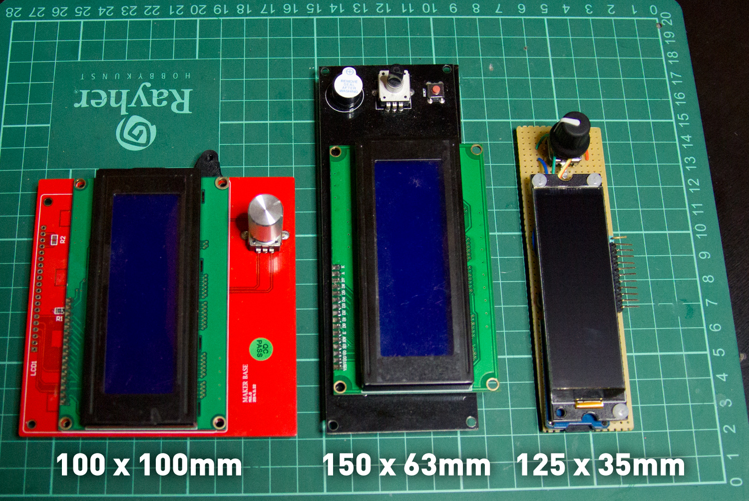
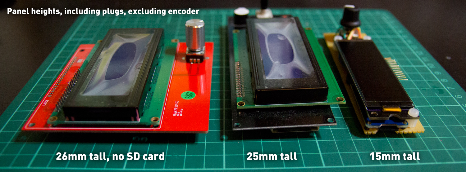
Not only is my custom controller smaller - it’s also thinner despite using standard components on a perfboard:
Is it worth it? I think so, but it could certainly be a good product just to sell a super-thin controller like this. I only need a single one, so it’s not for me , but someone should make a standard reprap controller that looks as good as the Panucatt Viki LCD, but with an OLED 😊
Next up: printing a nice enclosure for it!
Useful reading
Here’s some links that I found useful when solving this project:
Partial description on how to do this http://www.justblair.co.uk/attaching-a-lcd-display-and-rotary-encoder-to-a-ramps-controlled-reprap-printer.html
#define’s & pre-processing http://www.cplusplus.com/doc/tutorial/preprocessor/
Schematics for UltiPanel with rotary encoder http://www.thingiverse.com/thing:15081
This also gave me a chance to do some extra documentation around the Megatronics 2.0 electronics that I use for the printer.