Review of HiGrow ESP32 moisture and temperature sensor
20 July 2019 at 11:09 pm
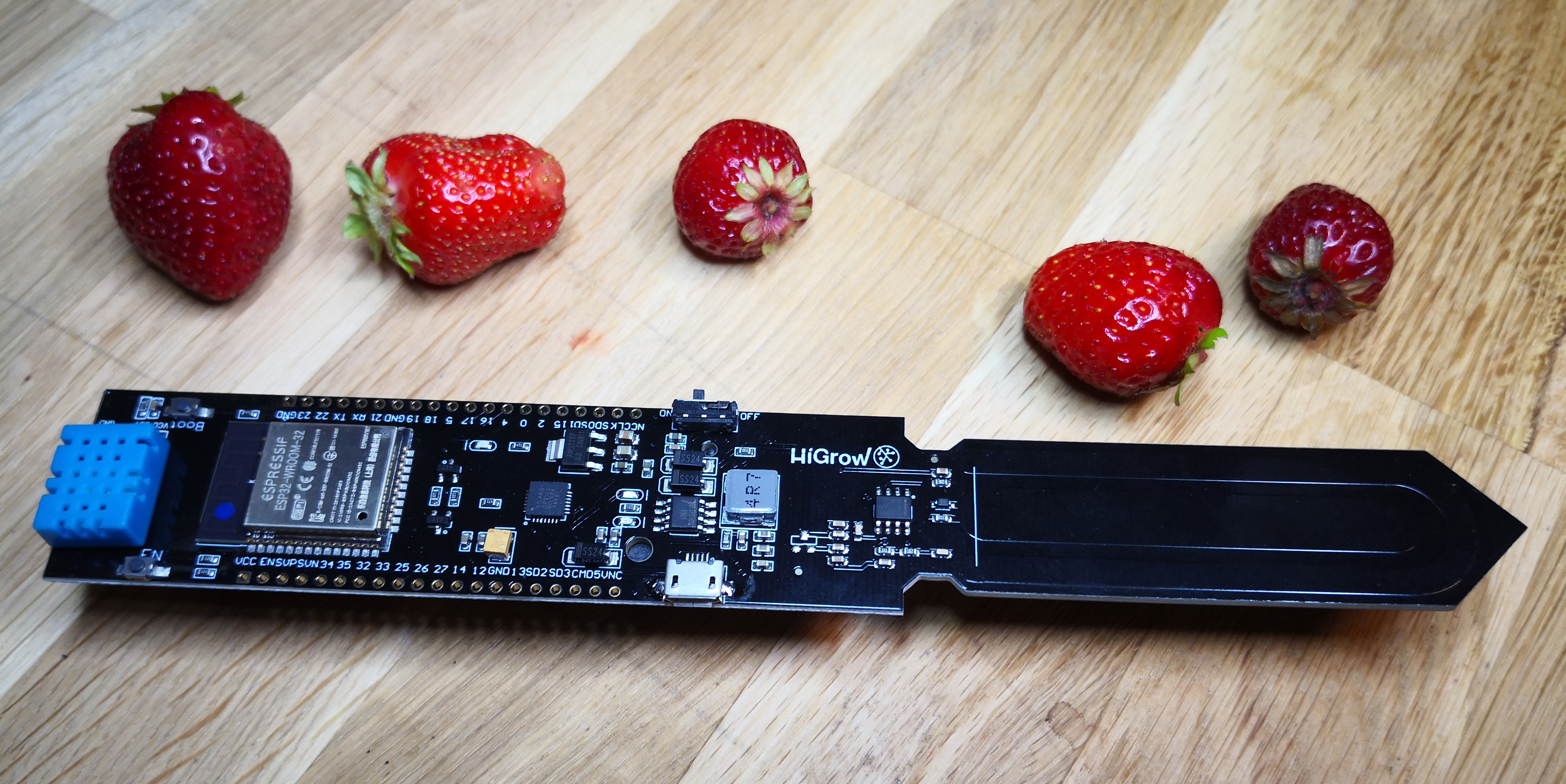
This summer I’m researching plant monitoring using IoT devices running on solar power. One of the obvious boards to test is the HiGrow boards you’ll find on asian websites. There’s not much info around on these, so I’m documenting my findings in this post.
Update November 2019: HiGrow afterthoughts
For this autumn I want my M2M (Machine to Machine Communication) students to work with plant monitoring. Given that plants are happy if they have access to some minerals, UV rich light and moisture, it should be fairly simple to set up a tiny IoT “farm” somewhere on the new premises of the school. For this to work, I’ll need an inexpensive board that I can hand out to the students.
Browsing AliExpress, DX, Banggood and similar sites for moisture sensors that you can control yourself, will typically return one of two results that come at a good price. Both are based on the same Open Hardware design and the original creator has closed down the project. Of the two boards found online, one is just the sensor and the other is the HiGrow board that comes with a full ESP32 onboard.
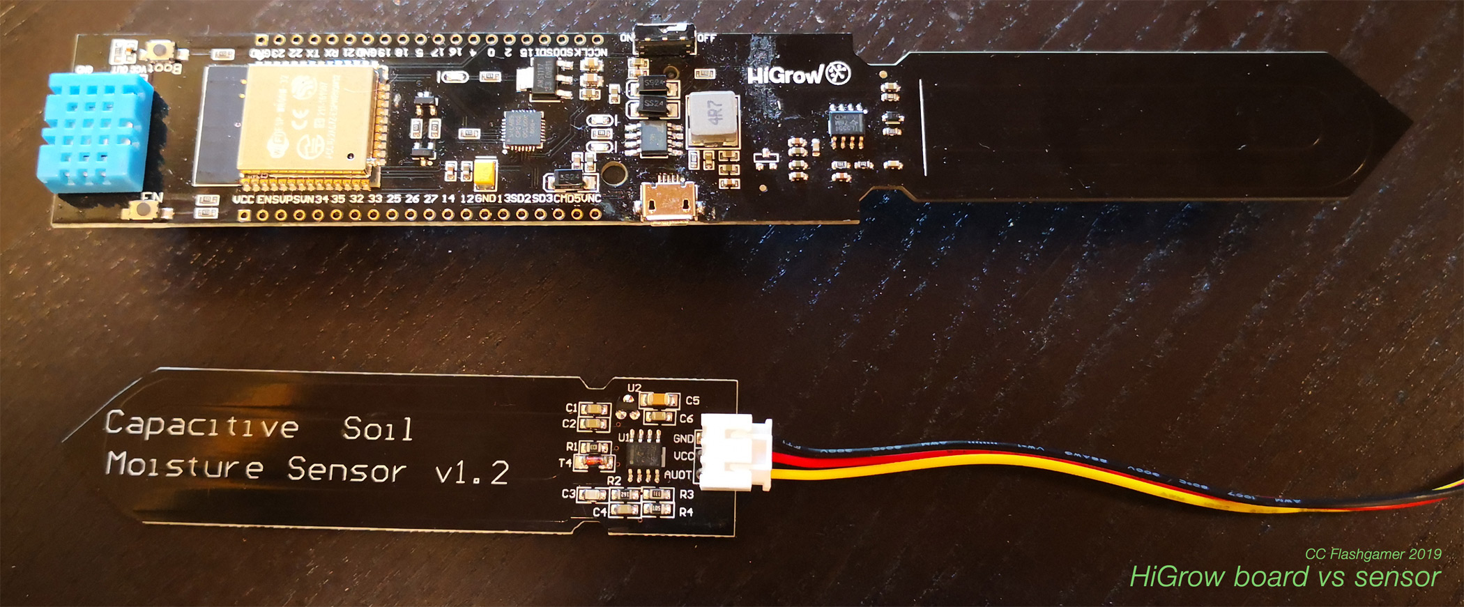
The sensor is about a dollar and the ESP32-based version is around ten dollars. Of these two, it’s more convenient with an integrated solution so I’ll focus on the HiGrow board though the sensor is a good alternative if you want to keep the microcontroller out of contact with the soil.
Here’s shortcuts to what I’ve found this far:
- HiGrow board features
- Power consumption & other drawbacks
- Updating the HiGrow firmware
- Why Capacitive sensing?
- Typical values for sand, mulch & soil
- HiGrow origins and status
- Project update: 10th Aug 2019
HiGrow features
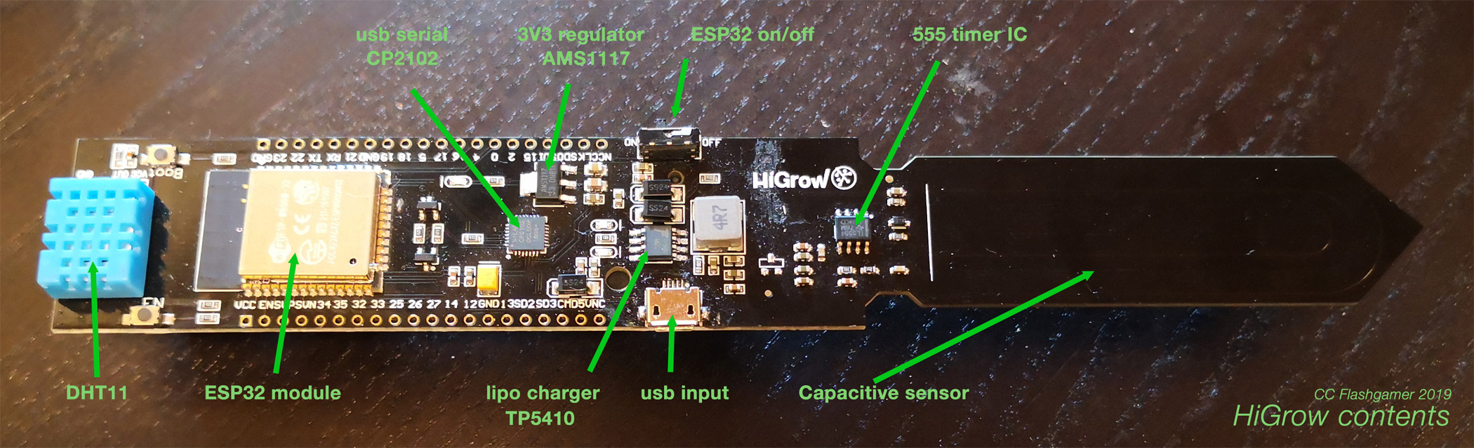
The HiGrow is a complete development board for monitoring plants. Here’s a list of the features you get for about $10:
- Espressif Wroom 32 rev 1 module (pinout). A powerful 32 bit microcontroller running at 80Mhz with WiFi radio and PCB antenna.
- CP2102 serial chip for programming the ESP32
- TP5410 lipo charger that’ll charge an optional 18650 lipo cell. The board contains two status LEDs showing charge status (red=not charging, green=charging)
- DHT11 humidity and temp sensor on gpio/pin 22.
- Capacitive sensor on gpio/pin 32 / analog pin 6
- User LED on gpio/pin 16
- Power switch
That’s all there is. The main sensor on the board is a capacitive moisture sensor based on a 555 timer generating an analog value based on capacitance. The sensing is fairly simple but works well. The board also holds a (fake) DHT11 sensor that can measure temperature and humidity fairly precisely. Using these two sensors, you can to some degree know if it has been raining recently (increased moisture) or if the sun is shining by comparing the reported temperature to weather data online. Not super precise, but good enough to know if your plants need water.
The user LED and power switch may seem insignificant, but they are indeed useful for debugging and programming. The LED can be used to show the status when you are out in the field and do not have a USB cable connected. The power switch is very handy for doing a hard reset if the ESP module throws programming errors when you try to program it.
You’ll find other sketches that indicate that there should be power monitoring on pin 34 and a light sensor on pin 33. This is for the V2 board that is not commercially available.
Power consumption & other drawbacks
On startup, the board pulls about 130mA, but over time it stabilises around 45-50mA. Without Wifi enabled, the board will pull about 20mA. These are theoretical numbers and after a lot of testing, I’ve found that these boards can pull from 170-270 mA given some conditions.
This video by Mark Furneaux details some of the drawbacks of this board. Here are some of his findings:
- Using MicroPython also works, but is a little inefficient
- Despite enabling Deep Sleep on the ESP32 it will still consume 20mA since the sensors are always on. This limits how long you can run the board using the 18650 lipo battery it comes with.
- The board isn’t very well protected against the elements, so it is limited to indoor use unless you improve it in some way
Mark published his video in November 2017, so I’m guessing he didn’t have time to take this project further? He also mentions production issues such as poor soldering. I see the same on my two boards, but I also noticed that the DHT11 sensor does not look original. Based on my testing, this part really does not hold up. My two units measure temperature with 4 Celcius in deviation. Capacitance measurements have a similar deviation and the Humidity is completely off for one of my two units. I’ll remove this DHT11 and replace it with a sensor that I know is good. I also had a USB connector fall off one of my boards, so the soldering is quite shoddy.
Programming these boards can be finicky. I can only get the board to program 1 in 3 times and only at 115200 baud or lower. This is not on par with other ESP32’s I have, so my guess is that something is done incorrectly on this PCB.
Updating the HiGrow firmware
Since the board is based on the wroom-32 module, it’s very straightforward to work with.
- Setup your Arduino IDE for ESP32 support according to the instructions found at the official Espressif Github
- Select a generic ESP32 board such as the Lolin D32 and set upload speed to 115200 since the default 921600 won’t be stable
- Grab a very basic sketch from my Gist or fix the deep-sleep parts of the official sketch
That’s all you need to upload and play around with it. I’ve also made a few more examples:
- Simple webserver to check in on your plant
- Thingspeak example (install Thingspeak Communication Library using the Library Manager)
Why Capacitive sensing?
The most basic moisture sensor is just two nails with wires connecting them to a microcontroller. You can get these $1 sensors that is basically just a PCB that does the same as those nails. The problem with these sensors is that they will corrode and may even in som cases affect the plant negatively. Capacitive sensors on the other hand does not affect the plant in any way and they have the potential to last for a long time. Andreas Spiess has a great video explaining the difference between these sensor types.
Typical capacitance values for sand, mulch & soil
I’ve done some preliminary testing using sand, mulch & soil and the table below lists some typical values. A typical value for the sensor not touching anything is above 3100. If touching very wet medium, the value can dip to below 1500. Keep in mind that this is just a very rough scale to give an die of the output values you can expect from the 10bit ADC on the ESP32.
| sand | mulch/soil | |
|---|---|---|
| Dry | 2747 | 2958 |
| Slight moisture | 2501 | 2731 |
| Moist | 2108 | 2362 |
| Very moist | 1636 | 1856 |
| Wet/soaking | 1513 | 1488 |
I’m working on a more precise test, but this should give you an idea.
If the board is online, you can see live values at the moment at https://thingspeak.com/channels/838228. I have a second reference board and it seems the output from the sensors can vary a bit. I think I’ll have to do some more testing to see how big the variance typically is.
HiGrow origins and status
The project seems to have originated from Github user @lucafabbri who created code for both both Arduino (no longer compiles) and Mongoose OS. Based on info found in the issue list for the Arduino code and the original Hackaday post, it seems that he is also the originator of the PCB design given that he mentions a V2 design? The project website higrow.tech is now deleted and the domain is for sale. The Arduino version of the code was last updated 2 years ago. The Mongoose OS version was last more than a year ago, so I can only guess that he didn’t have time to maintain the project and complete version 2?
Well, thanks to Chinese websites it seems the HiGrow design will be around for some time. If you need a better maintained project - Catnip electronics on Tindie seems to be on the right path. For now, the HiGrow board is sufficient for my use.
Project update: 10th Aug 2019
The more I use this board, the more I dislike it? As mentioned before, the soldering quality is subpar and both my two boards are now defect. One got a short after I changed it to use the DHT22 over DHT11. I did my best to resolve the short, but I failed. Both the red and green LED would turn on and the AMS1177-3.3 regulator got really hot. I replaced the regulator with a new one, but the short was still there. Without a schematic, it’s hard to troubleshoot but I figured it might be one of the decoupling caps on the power so I carefully removed these one by one (they’re tiny!). 5V was shorted to GND and I couldn’t figure out where it was. I gave it up.
The other board first lost it’s USB connector when I put the board into the 3D printed Higrow enclosure I designed. I’ve since remodelled the design to prevent this from happening, but next I got another problem - a small capacitor physically broke off the board. It also detached part of the cap itself and without knowing what cap to use, it’s next to impossible to fix. This was due to another error in my design that made the 3D model butt up against this part rather than the PCB itself. I’ll fix that in the design now and republish to Youmagine. The DHT11 and ESP32 on the board is still working, so I’m now using it to test my solar setup and how waterproof the 3D printed enclosure needs to be. It will be live here until it dies from water ingress.
I now have 2 new boards on order, so It’ll be a few days until I can the Higrow board again. I’ll now do more testing on the capacitive sensors (without MCU) while I wait for these.
Project update: 24th Nov 2019
Here's my HiGrow afterthoughts and why you probably should avoid it.