Teensy 3.2 Kicad example
05 July 2020 at 3:32 pm
So you want to make a DIY Teensy? Here’s some files to use as a starting point and a few things I learned while doing my first Teensy 3.2 based board.
Feel free to use the files on my Github as a reference design for your own Teensy 3.2. The board only has a few of the 30+ possible pins broken out, but I2C, SPI and Serial are all broken out along with some general pins. This turns it into a useful starting point if you are evaluating using Teensy in a product or just want to roll a custom board.
Designing the board
I found Phillips writeup really useful, but I used the original 3.2 schematic as my basis designing the board. Phillip’s post is already some years old, but its full of good advice. He has a special focus on the crystal. It’s always a good idea not to route signals near a crystal, but I do not think that it’s required to put a ground plane underneath. Also, the data lines for USB 2.0 do not have to be exactly the same length. Plus/minus a few millimeters is still good at these low speeds and most MCU’s are quite accommodating with regards to this. This board still follows the recommendations, but other designs that I have made are working well without an extra ground plane under the crystal. Just make sure that you do not have signals crossing either the D+/D- data lines or the signals from the crystal.
The Kicad files contains the Manufacturer Part Number (MPN) for the parts that are not completely generic. For capacitors, resistors and ferrites, you can use what you have. Most of the parts are in 0603 format, with a couple in 0805 (since these were cheaper in that size). You can likely make this much smaller using 0402 or even 0201, but my board can easily be soldered by hand given some magnification. The pinout is just as on the official Teensy 3.2, but the test LED is on digital pin 7 and there is a button attached to digital pin 28.
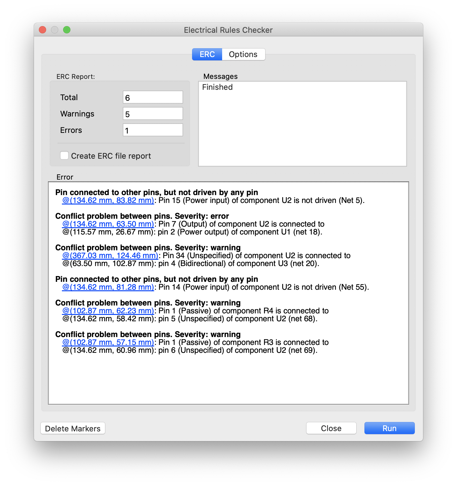
When running the Electrical Rules Checker (ERC), you’ll get a few errors. Most of these stem from incorrect definitions in the MK20DX256VLH7 Kicad symbol from Ultra Librarian. I’ve had this for almost all the symbols I download from them. I dunno what they are doing wrong, but I didn’t correct the symbol this time.
The warnings can be ignored and the error for VOUT33 is correct. This pin will output 3.3V/100mA if you apply 5V to VREGIN, but since I use 3.3V from a regulator in my design, it really is to be connected to the 3V3 power net, so the error is still good.
Board bringup - look for the heartbeat
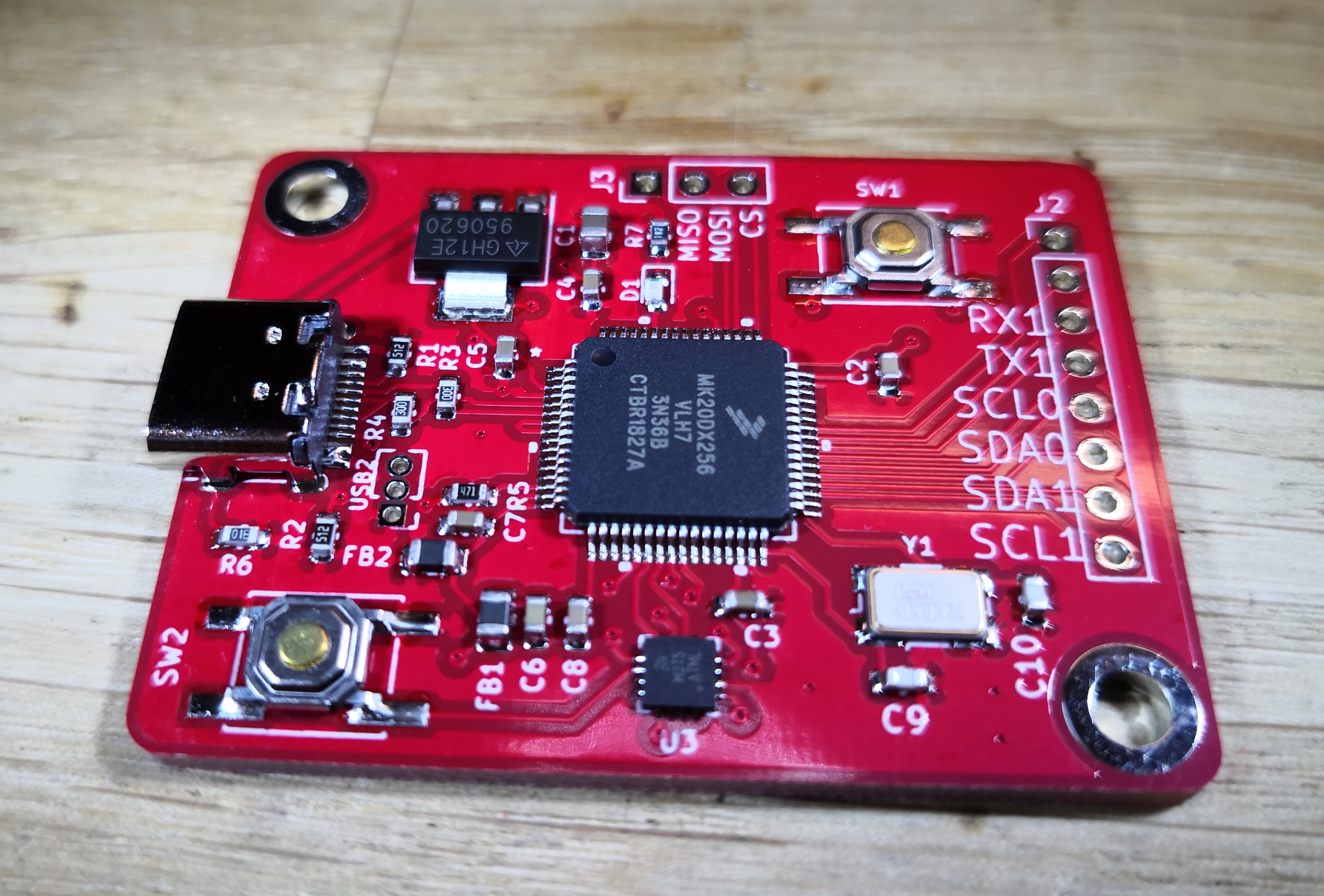
Soldering the board should be fairly easy. Most parts can be soldered by hand, but the MKL02 chip will likely require Hot air reflow. There are no special instructions. Just start with the smallest parts and solder one by one. This board has a USB Type C connector (as do all my designs from now) for the USB 2.0 connection and power. You can pick these up from LCSC, but the footprint is quite standard so connectors from many other brands will work.
As always - before applying power, make sure there’s no short circuits on your Power inputs. Measure 3V3 to GND, 5V input to GND using the continuity tester on your multimeter. If you have no shorts here, it’s likely safe to power the board since any I/O pin will survive being connected to 3V3.
The MKL02/MKL04 chip that you purchased from PJRC has the firmware required to wake up the main processor (MK20). You cannot use a MKL02Z32 from Digikey, as it will not have the required bootloader firmware. To check if the bootloader chip is working as intended, you’ll need an Oscilloscope with at least 20Mhz bandwidth. First measure the VSS & VDD pins to ensure that the IC has power. Next, connect your Oscilloscope GND to the board GND and measure the RESET_B pin as explained here.
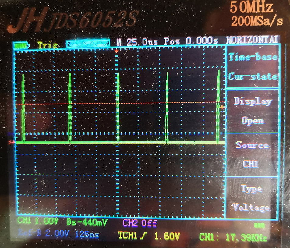
You should see a “heartbeat” signal like this if the MKL02/MKL04 chip is working as it should.
Confirm that the the main chip is working
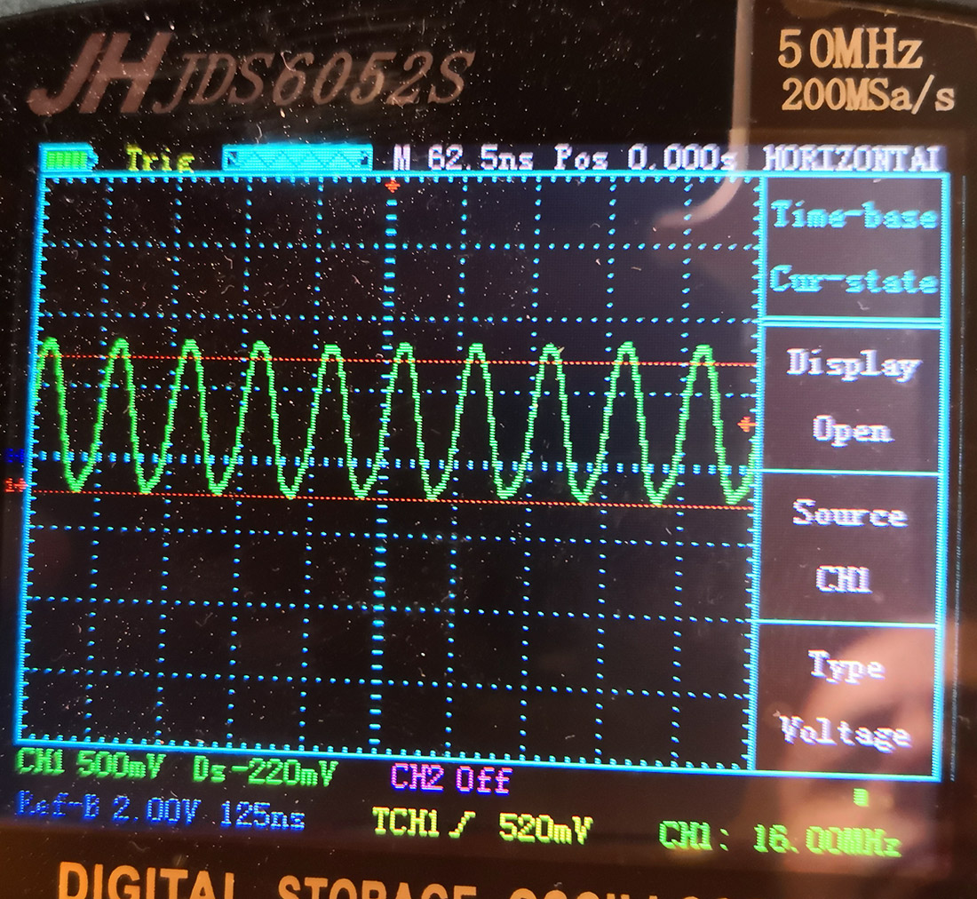
Pressing the PROGRAM button on your board should make the RESET_B line go high and stay high (3V3). This is what will turn your blank MK20 into a Teensy. This will start the crystal on the MK20, so if you measure the crystal, it should now be resonating at 16Mhz. At this point, the device should show up on your computer as a Teensy USB device.
Still problems?
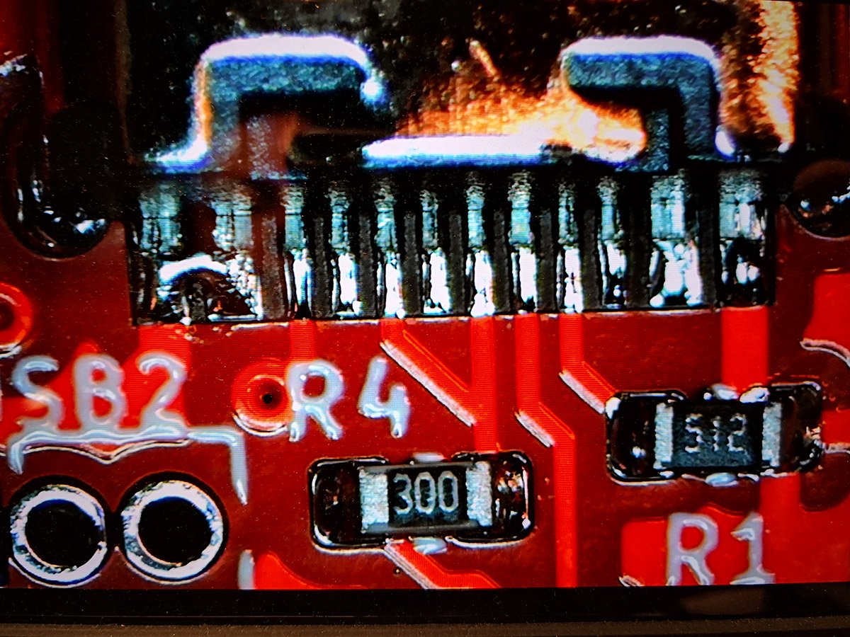
Visually inspect the board and check for short circuits. I missed the tiny short that can be seen on the microscope picture below. For an I/O pin, this won’t be a problem since no pins should be outputs by default and they can handle 3V3 as an input.
My first version of the board also had the USB data lines swapped. I have no idea why I didn’t double check that, as I’ll usually check all pins several times but I just couldn’t get the board to show up on my Mac. As soon as the lines were swapped, it worked right away.
If you’re building your own board based on this, feel free to ask me questions on Twitter?